


EPSON Stylus PHOTO 810/820/830 Revision B
Operating Principles Overview 28
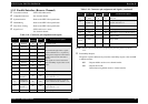
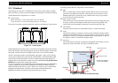
2.1 Overview
This section describes the operating principles of the Printer mechanism and electrical
circuit boards. Like the previous printers (Stylus COLOR 480/580), the Stylus PHOTO
810/820 has only the following two circuit boards and does not have the control panel
board.
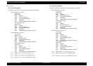
*1
Main board
(Stylus Photo 810/820)
: C417/C418 Main/Main-B board
*2
Main board
(Stylus Photo 820/830)
: C483/484 Main-B board
Power supply board
(Stylus Photo 810/820)
: C417 PSB/PSE board
Power supply board
(Stylus Photo 820/830)
: C482 PSH (For 42V)
*1
: Due to this, the Stylus COLOR 480/580 does not have switches (Power, Error reset,
Ink cartridge replacement) and LEDs. However, the Stylus PHOTO 810/820 has
them on the C418 Main board instead of the control panel board.
*2
: C418 Main/Main-B board is used for the Stylus C60 and Stylus Photo 810/820.
However, there is difference of ASIC & PROM mounted on the C418 Main/
Main-B board between the Stylus C60 and the Stylus Photo 810/820.
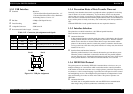
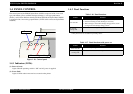
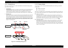
2.1.1 Printer Mechanism
The Printer mechanism for the Stylus PHOTO 810/820 is newly designed. But, the
basic component of the Printer mechanism is almost the same as the previous printer
(Stylus COLOR 480/580). And also, Stylus Photo 820/830 is successor to Stylus Photo
810/820 and is the same as its printer mechanism.
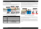
This printer consists of Printhead, Carriage mechanism, Paper loading mechanism,
Paper feeding mechanism, Ink system (Pump mechanism including newly designed
Carriage lock mechanism, Capping mechanism including newly designed Wiper
mechanism).
Like the previous printers (Stylus COLOR 480/580), the Stylus PHOTO 810/820 is
equipped with two stepping motors; one for the Paper loading/feeding mechanism and
the Pump mechanism with the CR lock mechanism, and one for the CR mechanism.
The ASF unit for the Paper loading mechanism uses rear entry front eject system. And,
single LD roller in Holder shaft unit loads a paper to the Printer mechanism.
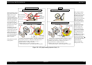
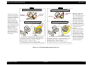
The Cap unit which adopts the valveless mechanism is newly designed on this printer
as follows.
No porous pad in cap
Cap unit with wiper
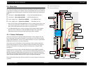
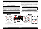
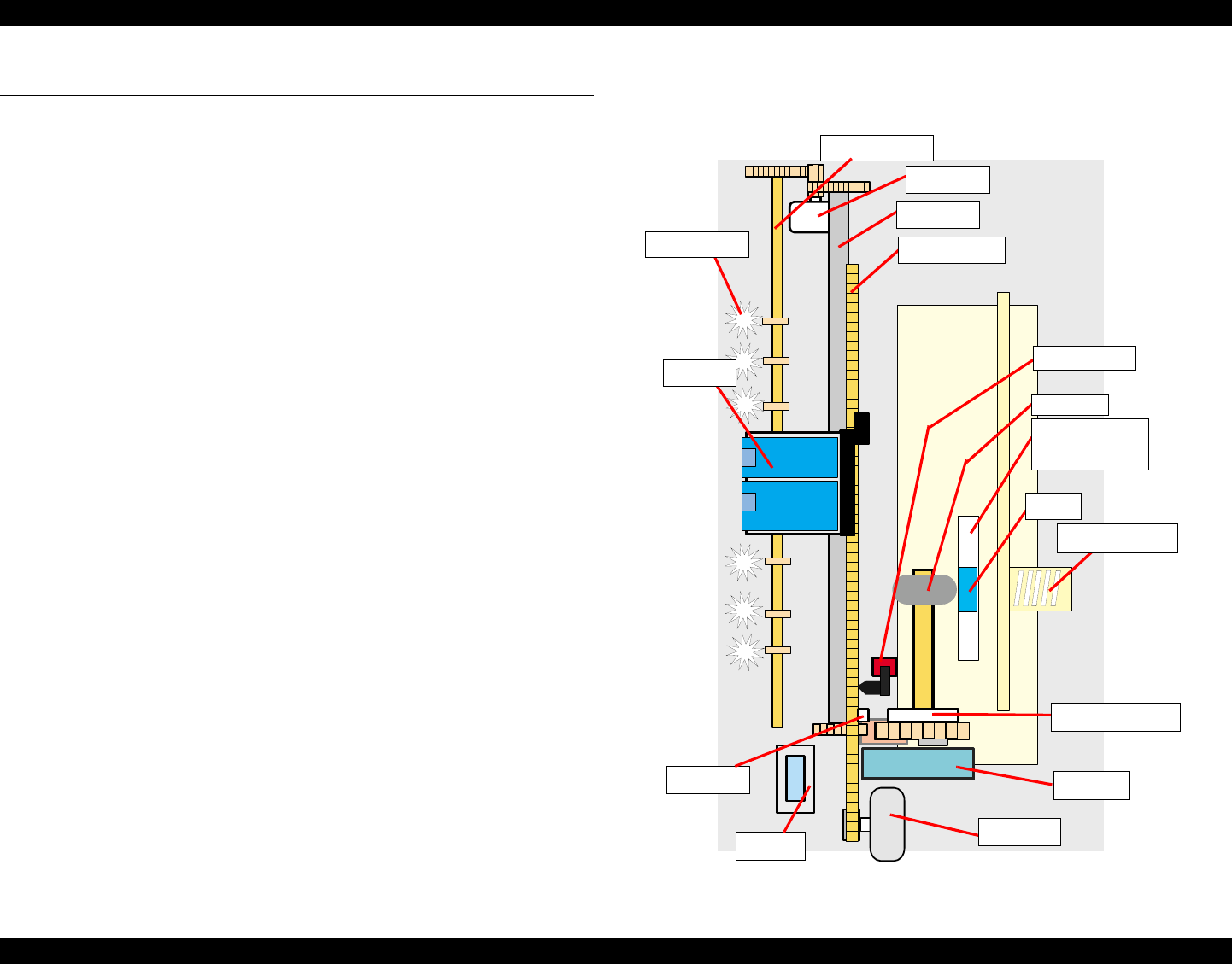
Figure 2-1. Printer mechanism block diagram
Compression spring
CR motor
Pad holder
(Paper return plate)
LD pad
Clutch mechanism
CR unit
PF rolle
r
HP/PE Sensor
LD Roller
Pump unit
Paper eject roller
Star wheel roller
CR timing belt
Cap unit
PF motor
Change lever