


EPSON Stylus PHOTO 810/820/830 Revision B
PRODUCT DESCRIPTION INTERFACE 18
* A low logic level on the Logic H signal is 2.0V or less when the printer
is powered off and this signal is equal or exceeding 3.0V when the
printer is powered on. The receiver shall provide an impedance
equivalent to 7.5K ohm to ground.
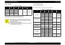
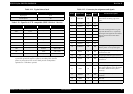
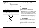
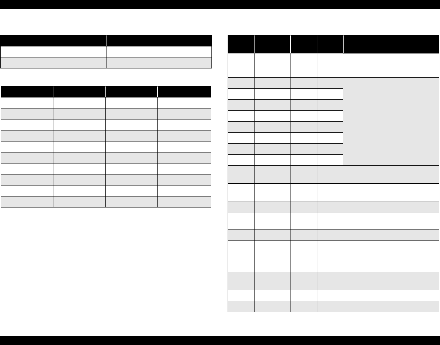
Table 1-11. Typical time of tack
Parallel I/F mode Typical time of tack
High Speed 0.5us
Normal Speed 2us
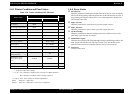
Table 1-12. Signal level: TTL compatible (IEEE-1284 level 1 device)
Parameter Minimum Maximum Condition
VOH* - 5.5V
VOL* -0.5V -
IOH* - 0.32mA VOH = 2.4V
IOL* - 12mA VOL = 0.4V
CO - 50pF
VIH - 2.0V
VIL 0.8V -
IIH - 0.32mA VIH = 2.0V
IIL - 12mA VIL = 0.8V
CI - 50pF
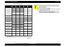
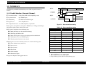
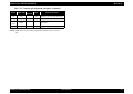
Table 1-13. Connector pin assignment and signals
Pin No. Signal name
Return
GND pin
In/Out Functional description
1 -STROBE 19 In
The strobe pulse. Read-in of data is
performed at the falling edge of this
pulse.
2 DATA0 20 In
The DATA0 through DATA7 signals
represent data bits 0 to 7, respectively.
Each signal is at high level when data is
logical 1 and low level when data is
logical 0.
3 DATA1 21 In
4 DATA2 22 In
5 DATA3 23 In
6 DATA4 24 In
7 DATA5 25 In
8 DATA6 26 In
9 DATA7 27 In
10 -ACKNLG 28 Out
This signal is a negative pulse indicating
that the printer can accept data again.
11 BUSY 29 Out
A high signal indicates that the printer
cannot receive data.
12 PE 28 Out A high signal indicates paper-out error.
13 SLCT 28 Out
Always at high level when the printer is
powered on.
14 -AFXT 30 In Not used.
31 -INIT 30 In
The falling edge of a negative pulse or a
low signal on this line causes the printer
to initialize. Minimum 50us pulse is
necessary.
32 -ERROR 29 Out
A low signal indicates printer error
condition.
36 -SLIN 30 In Not used.
18 Logic H - Out Pulled up to +5V via 3.9 K ohm resistor.