


EPSON Stylus PHOTO 810/820/830 Revision B
Appendix Connector Summary 137
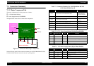
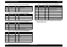
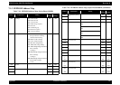
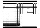
Table 7-5. CN4 - HP/PE sensor (Stylus Photo 820/830)
* Pin No.1/3 is different between Stylus Photo 810/820and Stylus Photo 820/830.
- Stylus Photo 810/820 : GND
- Stylus Photo 820/830 : GND2
Table 7-4. CN4 - HP/PE Sensor (Stylus Photo 810/820)
Pin Signal Name I/O Function
1 HPPE In Sensor detect signal
2 GND --- Ground
3 HPPEV --- Sensor Power Supply
Pin Signal name I/O Function
1 HP In/Out Sensor detection signal
2 GND --- Ground
3 SENV --- Sensor power supply
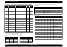
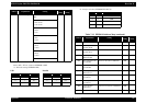
Table 7-6. CN7 - PF Motor (Stylus Photo 810/820/830)
Pin Signal Name I/O Function
1 PFA Out Phase drive signal (A)
2 PFB Out Phase drive signal (-A)
3 PF-A Out Phase drive signal (B)
4 PF-B Out Phase drive signal (-B)
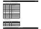
Table 7-7. CN8 - Printhead (Stylus Photo 810/820/830)
Pin Signal Name I/O Function
1 GND (GND2)* --- Ground
2 COM --- Head drive pulse (
trapezoid waveform)
3 GND (GND2)* --- Ground
4 VHV --- -42 V power supply for nozzle selector
5 GND --- Ground
6 NCHG Out All nozzle fire selection pulse
7 GND --- Ground
8 LAT Out Head data latch pulse output
9 VDD3.3 --- Logic power supply (+3.3V)
10 CSCK Out Clock signal for EEPROM
11 COI In I/C detection signal
12 CRST Out Reset signal for EEPROM
13 THM In Thermistor detection signal
14 CSDA In/Out CSIC data signal for EEPROM
15 CVDD --- Logic power supply (+3.3V) for EEPROM
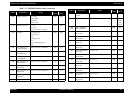
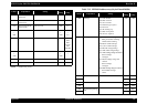
Table 7-7. CN8 - Printhead (Stylus Photo 810/820/830)
Pin Signal Name I/O Function