


EPSON Stylus PHOTO 810/820/830 Revision B
Disassembly and Assembly Disassembly 105
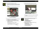
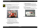
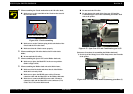
7. Remove the Upper power supply board from the Lower power supply board shield
plate.
When assembling the Power supply board to the Lower power
supply board shield plate,
Make sure to install the Power supply board correctly.
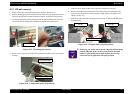
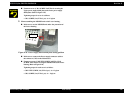
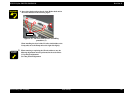
Fasten three screws (C.B.S. SCREW 3x6 F/Zn, C.C.S-TITE
SCREW 3x6 F/Zn, C.B.(O). SCREW 4x5 F/Zg) for securing
the Power supply board and the earth wire to the Lower
power supply board shield plate in the order indicated in the
following figure.
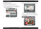
Figure 4-27. Tightening procedure for the PSB/PSE board
Tightening torque for each screw is as follows.
•
C.B.(O). SCREW, 4x5, F/Zg (1 pcs) : 11 ± 1 kgf.cm
•
C.B.S. SCREW, 3x6, F/Zn (2 pcs) : 6 ± 1 kgf.cm
•
C.B.S-TITE SCREW, 3x6, F/Zn (1 pcs) : 6 ± 1 kgf.cm
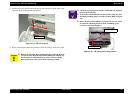
Make sure to place three wires of the AC cable away from
the Transformer and the Heart sink on the Power supply
board. (Refer to Figure 4-27)
2
1
3
4
Heat sink
Transformer
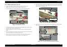
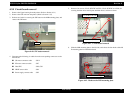
Make sure to set the Power supply radiator in the correct
position. (Refer to Figure 4-27)
Make sure to set the earth wire on the dowel of the Lower
power supply board shield plate (Refer to Figure 4-26)
(* The product with 110V type AC cable does not have the earth
line)
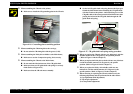
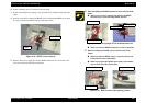
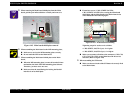
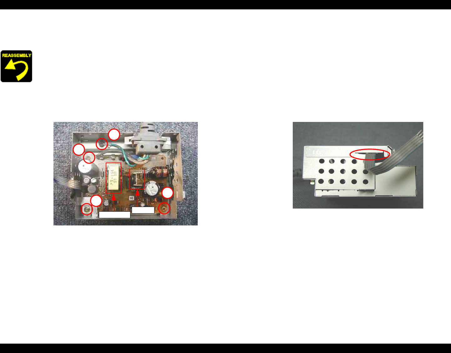
When assembling the Upper power supply shield plate to the
Lower power supply shield plate,
Make sure to place the Power supply connector cable in the
space between both power supper shield plates.
Figure 4-28. Power supply connector cable setting position