


EPSON Stylus PHOTO 810/820/830 Revision B
Disassembly and Assembly Disassembly 109
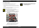
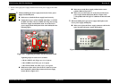
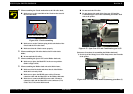
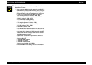
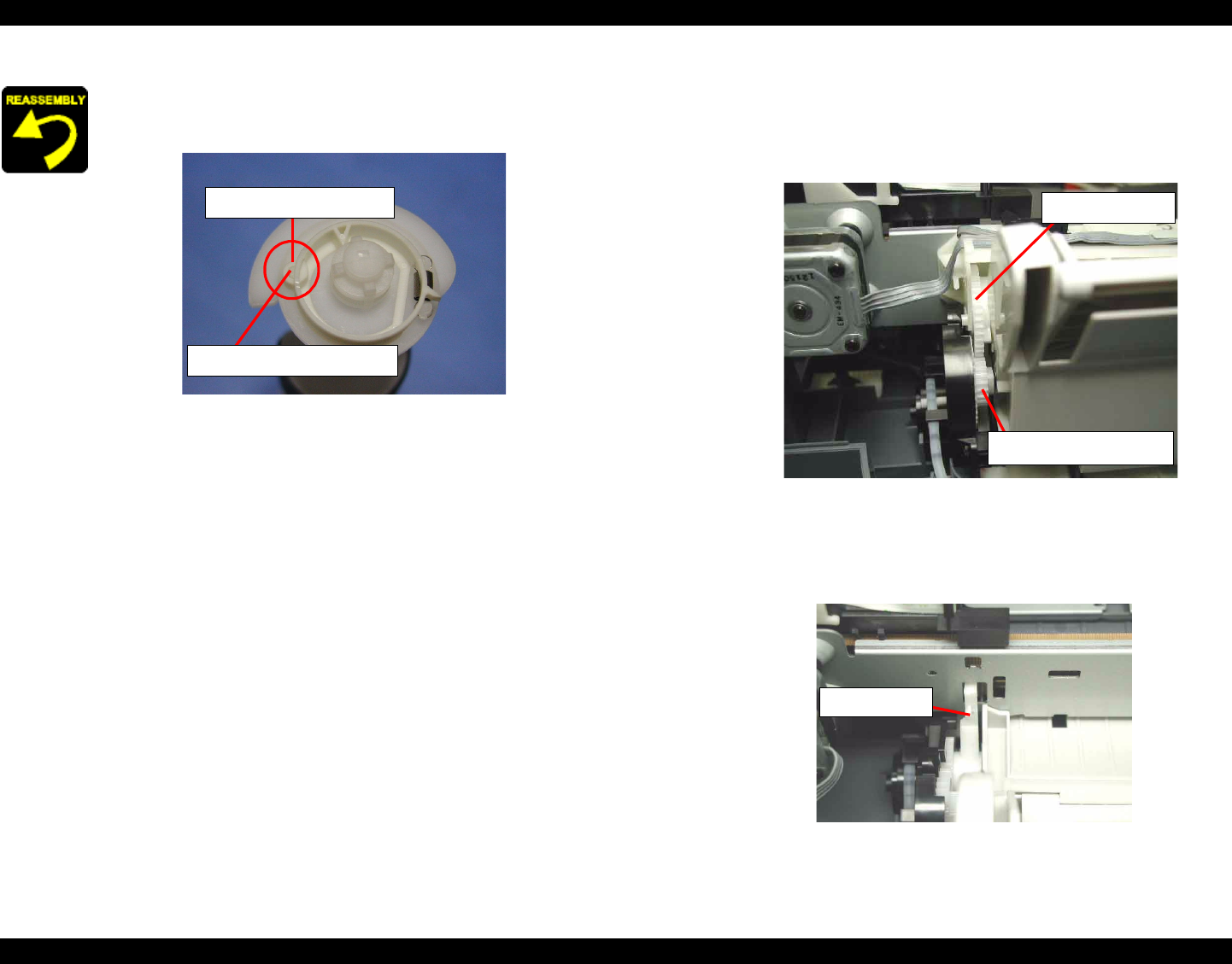
When assembling the Clutch mechanism to the LD roller shaft,
Make sure to set the round hole of the Clutch on the dowel of
the LD roller shaft.
Figure 4-36. Clutch assembling
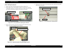
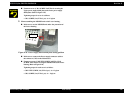
Make sure to set the Tension spring 0.143 to the hooks of the
Clutch and the LD roller shaft.
Make sure that the Clutch rotates properly.
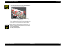
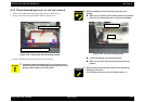
When assembling the LD roller shaft to the LD roller shaft
holder,
Do not touch the LD roller.
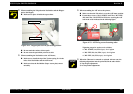
When assembling the Spacer FFC on the Holder shaft unit,
Make sure to place the Head FFC in the correct position.
(Refer to Figure 4-30)
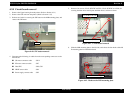
When assembling the Holder shaft unit to the Main frame,
Make sure that five hooks and three dowels of the Holder
shaft unit is correctly fixed.
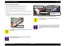
Make sure to place the HP/PE sensor cable, CR motor
connector cable and the Head FFC on the Holder shaft unit.
Make sure to connect the HP/PE sensor cable, CR motor
connector cable and the Head FFC to the connector (CN4,
CN8, CN9, CN12) on the Main board.
Round hole on the Clutch
Dowel on the LD roller shaft
Do not touch the LD roller.
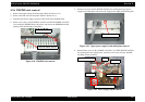
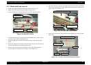
Do not damage the tooth of the Spur gear 35.2 and the
Combination gear 16.32 when assembling the Holder shaft
unit to the printer.
Figure 4-37. Spur Gear 35.2 and Combination gear 16.32
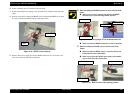
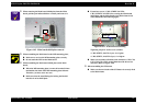
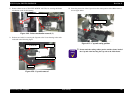
[Reference: Procedure for assembling the Holder shaft unit]
1) Set the tip of the Change lever in the Pump unit to the front side
of the printer.
Figure 4-38. LD roller shaft holder assembling procedure (1)
Spur gear 35.2
Combination gear 16.32
Change lever