


EPSON Stylus PHOTO 810/820/830 Revision B
Disassembly and Assembly Disassembly 97
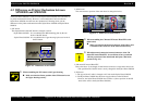
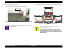
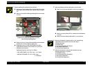
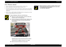
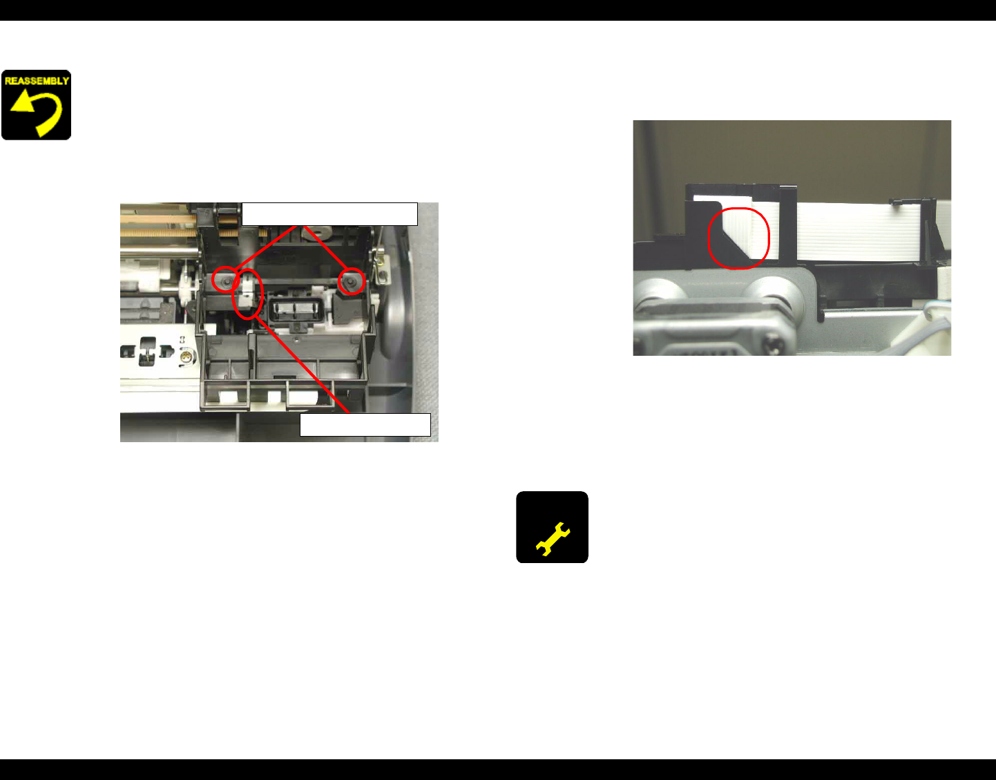
When assembling the Printhead to the CR unit,
Make sure to place the Head FFC on the Spacer FFC and the
cable holder on the left side of the CR unit. (Refer to Figure
4-7)
Make sure to install the Head grounding plate to the carriage
correctly.
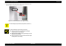
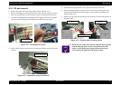
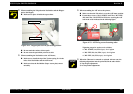
Figure 4-9. Printhead installation position
(pin & the grounding plate)
Make sure to fit two holes of the Printhead to the installation
position pins correctly. (Refer to Figure 4-9)
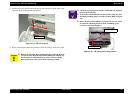
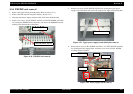
Fastening two screw (C.B.P-TITE SCREW 3x8 F/Zn,
+BIND B-TITE SEMS W2 2.5x5 F/Zb) for securing the
Printhead to the CR unit.
Tightening Torque for each screw is as follows.
•
C.B.P-TITE SCREW, 3 x 8, F/Zn (1 pcs) : 6 ± 1 kgf.cm
•
+BIND B-TITE SEMS, W2, 2.5 x 5, F/Zb (1 pcs) :
:
2 ± 0.5 kgf.cm
Head installation position pains
Head grounding plate
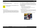
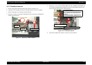
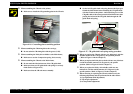
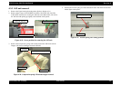
When assembling the Head cable holder to the CR unit,
Make sure to place the Head FFC in the correct position.
Figure 4-10. Head FFC setting position
Make sure that the Head FFC is connected to the Printhead
correctly.
Make sure that the Head cable holder is correctly fixed.
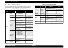
ADJUSTMENT
REQUIRED
When the Printhead is replaced with new one, the following
adjustments must be performed in the order below.
1) Initial ink charge
2) Head ID input
3) Gap adjustment (Bi-d adjustment)
4) Top margin adjustment
5) 1st dot position adjustment
When the Printhead is removed and reinstalled, only the
following adjustment is required.
1) Printhead cleaning
2) Gap adjustment (Bi-d adjustment)
3) Top margin adjustment
4) 1st dot position adjustment