


EPSON Stylus PHOTO 810/820/830 Revision B
Operating Principles Overview 39
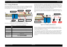
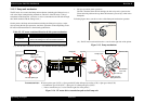
2.1.5.2 Pump unit mechanism
The PF motor also controls the Pump unit mechanism (including the Change lever) as
well as the Paper loading/feeding mechanism. The drive of the PF motor is always
transmitted to the Pump unit. (And also, its drive is transmitted to the LD roller through
the Clutch mechanism & the Change lever.)
On this printer, the Pump unit mechanism including the Change lever plays a major
role expecting the ink eject operation. And, these operations control depending on the
PF motor rotational direction as the following table below.
(*1): The PF motor rotational direction = seen from the left side of the printer.
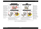
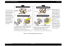
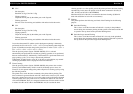
1. Ink eject operation (usual operation)
The ink is absorbed from the ink cartridge, the ink cavity and is ejected to the
Waste drain ink pad from the cap when the ink tube is pressed by a roller in the
Pump unit.
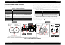
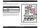
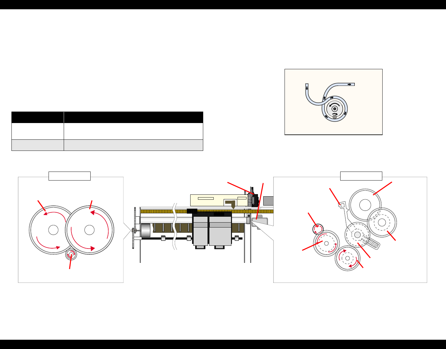
Following figure shows you the overview of the Pump unit mechanism operation
(*1): The PF motor rotational direction = seen from the right side of the printer.
Figure 2-13. Pump mechanism
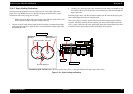
Transmission Path :
PF motor pinion gear (CCW) → Spur gear 60 (PF roller & Paper eject roller) (CW)→ Spur gear 10.8 (CCW)
→ Combination gear 18.28 (CW) → Spur gear 27.2 (Pump unit gear) (CCW)
( * Above transmission pass = seen from the right side of the printer)
Figure 2-14. PF motor drive transmission path to the Pump unit
Table 2-5. PF motor rotational direction & Ink system mechanism
Directions (*1) Functions
Clockwise
• Absorbs the ink by the Pump unit
• Release the Change lever from the Clutch mechanism
Counterclockwise
• Non operation
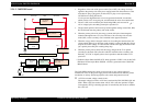
Cap unit side
Waste drain
Ink pad side
Change Lever
Spur Gear 35.2
Cap unit
Pump unit
Spur gear 60
(PF roller)
Combination
Gear 18.28
Spur Gear 25.6
PF roller
Spur Gear 27.2
(Pump Unit Gear)
Spur gear 60
(Paper eject roller)
PF motor pinion gear
Combination
Gear 16.32
Left side view Right side view