


EPSON Stylus PHOTO 810/820/830 Revision B
Operating Principles Electrical Circuit Operating Principles 42
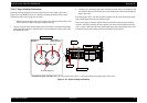
2.2 Electrical Circuit Operating Principles
The electric circuit of the Stylus Photo 810/820/830 consists of the following boards.
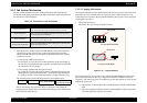
Main board:
Stylus Photo 810/820 : C417/C418 Main/Main-B
*1
Stylus Photo 820/830 : C483/C484 Main-B Board
*2
Power supply board:
Stylus Photo 810/820 : C417 PSB/PSE Board
Stylus Photo 820/830 : C482 PSH (For 42V)
*1
: C418 Main/Main-B board is used for both the Stylus C60 and the Stylus Photo
810/820. Followings show you the specification of the C418 Main/Main-B board.
- For the Stylus C60
1) C418 Main : 2 in 1 ASIC + Soldering SOJ ROM (from the first mass production)
2) C418 Main/Main-B : 3 in 1 ASIC + Soldering SOJ ROM (Running change)
- For the Stylus Photo 810/820
1) C418 Main/Main-B : 3 in 1 ASIC + Soldering SOJ ROM
(from the first mass production)
*2
: C483/C484 Main-B board is used for both the Stylus C61/C62/Photo 820/830.
Followings show you the specification of the C483/C484 Main-B board.
1) C483/C484 Main-B : 2 in 1 ASIC + Soldering SOJ ROM
(from the first mass production)
Note: CPU, ASIC and PROM is integrated as one chip (IC1) on the Main board.
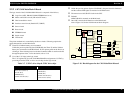
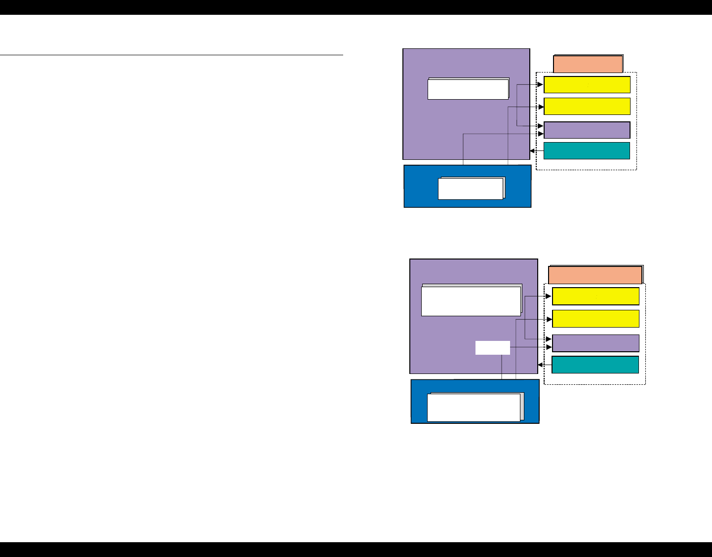
This section provides operating principles of C417/C418 Main, C417/C418 Main-B,
C483 /C484 Main-B board and C417 PSB/PSE, C482 PSH board. refer to Figure 2-15/
Figure 2-16 for the major connection of the each boards and their roles.
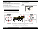
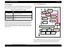
Figure 2-15. Electric circuit (Stylus Photo 810/820)
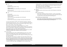
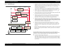
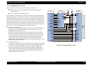
Figure 2-16. Electric circuit (Stylus Photo 820/830)
C418 Main board
C417 PSB/PSE board
HP/PE sensor
Head driver board
PF motor
CR motor
Printer mechanism
+5VDC
+42VDC
C418 Main board
C417 PSB/PSE board
HP/PE sensor
Head driver board
PF motor
CR motor
Printer mechanism
+42VDC
+3.3VDC