


EPSON Stylus PHOTO 810/820/830 Revision B
Disassembly and Assembly Disassembly 101
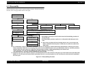
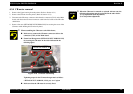
4.3.4 CR motor removal
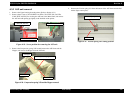
1. Remove the Upper housing from the printer. (Refer to Section 4.3.1)
2. Remove the CR unit from the printer. (Refer to Section 4.3.3)
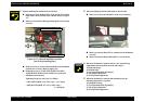
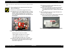
3. Disconnect the CR motor connector cable from the connector (CN12) on the Main
board, and release the CR motor connector cable from five hooks on the LD roller
shaft holder.
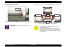
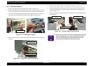
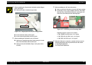
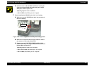
4. Remove four nots (HEXAGON NOT NORMAL M3) for securing the screw of the
CR motor while holding the CR motor by hand.
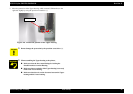
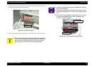
When assembling the CR motor to the Main frame,
Make sure to connect the CR motor connector cable to the
connector (CN12) on the Main board.
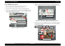
Fasten four Hexagon nut (HEXAGON NUT NORMAL M3)
for securing the CR motor in the order indicated in the
following figure.
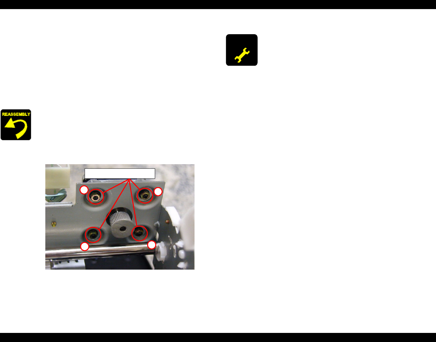
Figure 4-18. CR motor assembling
Tightening torque for the CR motor hexagon nut is as follows.
•
HEXAGON NUT, NORMAL, M3 (4 pcs) : 6 ± 1 kgf.cm
Make sure that the CR motor is correctly fixed.
HEXAGON NOT, NORMAL, M3
3
1
2
4
ADJUSTMENT
REQUIRED
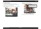
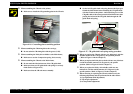
When the CR motor is removed or replaced with new one, the
following adjustment must be performed in the order below.
1) Gap adjustment (Bi-d adjustment)
2) 1st dot position adjustment