


EPSON Stylus PHOTO 810/820/830 Revision B
Operating Principles Electrical Circuit Operating Principles 57
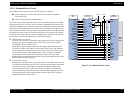
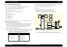
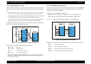
2.2.3.4 Reset Regulator Circuit
Reset IC (IC3) on the main board monitors the two voltage: +5V for the logic line and
+42V
for the drive line. Reset IC outputs the reset signal to CPU (IC8) in the following
case.
1. When the printer power is turned on and reset IC detects 4.2V on +5V line/35.8V
on +42V line, reset signal is output to perform the initialize operation correctly.
2. When the printer power is turned off and reset IC detects 4.2V on +5V line/35.8V
on +42V line, reset signal is output to stop the printer operation safely.
3. When reset IC detects 4.2V on +5V line/35.8V on +42V line with fail during the
printer operation, reset signal is output to stop the printer operation safely.
Unlike the previous products, the timer IC is not built in the reset IC and the Lithium
battery is not mounted on this MAIN board either.
.
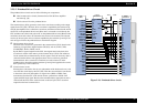
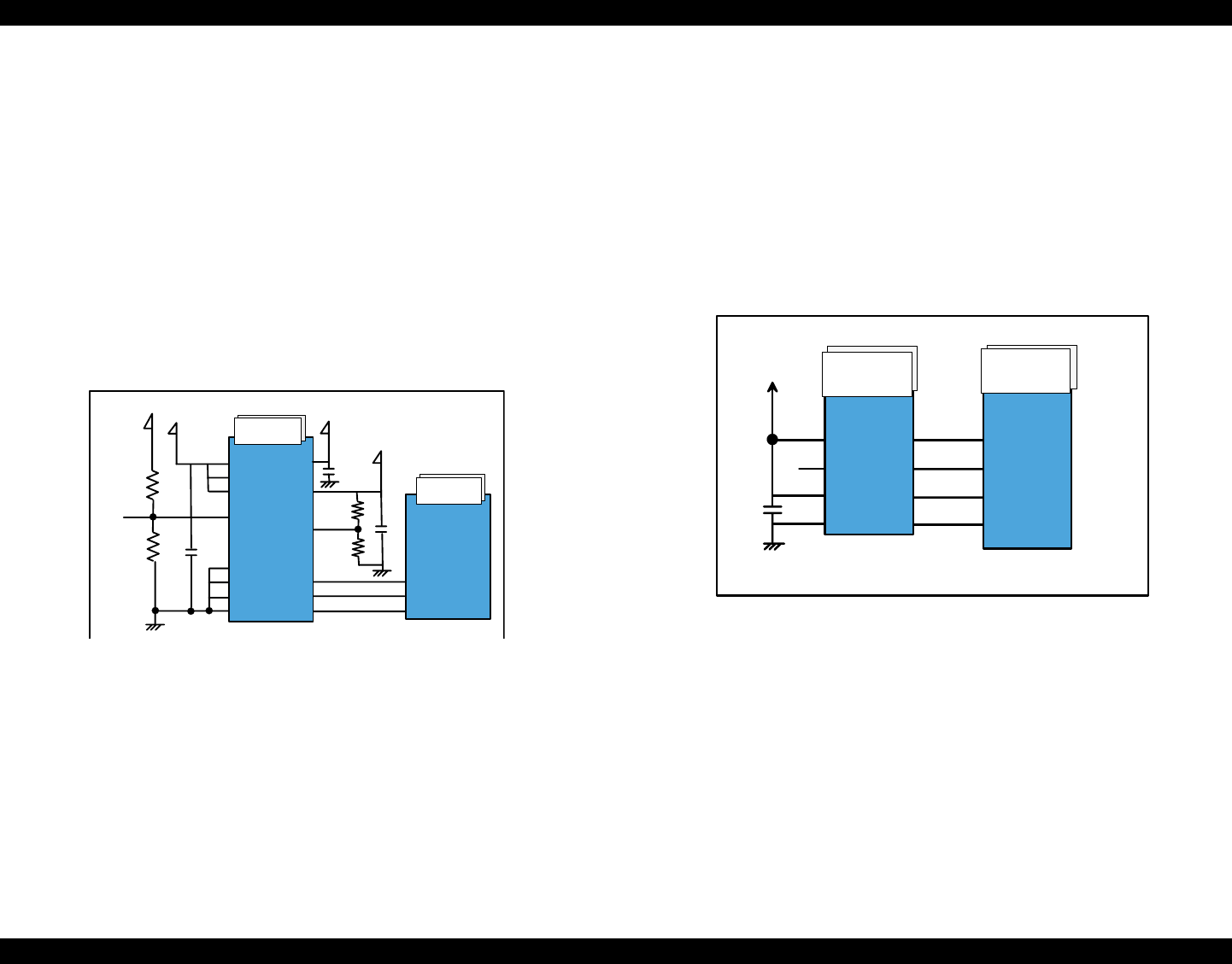
Figure 2-28. Reset Regulator circuit block diagram
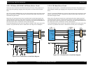
Main line for reset regulator IC has the following function.
VOUT1: Reset line
VOUT2: Interrupt signal
IN: +42V line monitoring line
VCC: +5V line monitoring line
*Unlike Stylus C50/C60, Stylus C61/C62 does not have exclusive regulator IC which
generates +3.3VDC from +5VDC. Instead of the regulator IC, this IC generates
+3.3VDC from +5VDC.
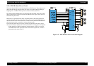
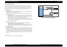
2.2.3.5 EEPROM Control Circuit
When the printer power is turned off, the following information is stored in EEPROM
(IC5) which is nonvolatile memory. And, when the printer power is on, CPU (IC8)
reads the information from EEPROM.
Information stored in EEPROM is listed below.
Various ink counter (I/C consumption counter, waste pad counter, etc.)
Mechanical setting value (Head ID, Bi-D adjustment, USB ID, etc.)
Refer to 7.1.2 that provides the detailed information stored in EEPROM.
Figure 2-29. EEPROM circuit diagram
EEPROM is connected to CPU with 4 lines and each line has the following function.
CS: Chip selection signal
CK: Data synchronism clock pulse
DI: Data writing line (serial data) at power off.
DO: Data reading line (serial data) at power on.
IC3
M62510FP
IC8
E01A37CB
+3.3V
+42V
4
+5V
VCC
Vin1
Vin2
3
12
IN
GND
GND
GND
GND
5
1
7
8
14
VOUT1
VOUT2
VD2
Vres
VOUT2
VOUT1
+1.5V
37
30
29
MRES
NMILVL
RESET
EEPROM-93C
(IC5)
E01A37CB
(IC8)
+.3.3V
VCC
NC
ORG
GND
CS
SK
DI
DO
C-P20
C-P21
C-P22
C-P23
136
135
134
133
1
2
3
4
8
7
6
5