


EPSON EPL-6200/EPL-6200L Revision A
Disassembly and Assembly Overview 132
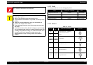
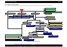
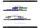
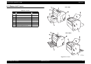
4.1.4 Main Unit Disassembly
The flowchart below shows step-by-step disassembly procedure. When disassembling each component, refer to the page number shown in the figure.
Flowchart 4-1. Disassembly Flowchart
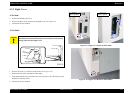
Right Cover (p.139)
Top Cover (p.142)
Main Board Assy (C533/C534 Main) (p.146)
Control Panel (p.150)
Protection Sheet Metal (p146)
Front Cover (p.141)
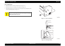
Left Cover (p.138)
Cooling Fan Motor (p.155) Main Motor (p.155)Paper Feed Solenoid (p.157)
MP Cassette (MP Tray) (p.140)
PH Unit (p.154)
Paper Exit Open/Close Cover (p.142)
Paper Exit Cover (p.143)
Upper Rear Cover (p.143)
Lower Rear Cover (p.144) Fuser Unit (p.152)
High Voltage Unit (HV1) (p.151)Power Supply Unit (PU1) (p.151)
Paper Feed Clutch Gear (p.158)
Fuser Unit Disassembly (p.153)
Paper Tray Empty Sensor
(EPL-6200 only) (p.156)
4.3 Removal of Covers (p137)
4.4 Removal and Installation of Circuit Boards (p145)
4.5 Removal and Installation of Major Components (p152)
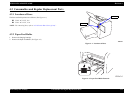
4.2 Consumables and Regular Replacement Parts (p134)
START
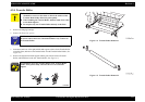
Paper Feed Roller (p.134)
Transfer Roller (p.136)
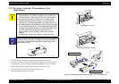
Developer Cartridge / Photoconductor Unit Replacement (p.
1
Output Tray (p.141)
Parallel I/F Board (EPL-6200) (p.149)
USB I/F Board (EPL-6200) (p.149)