


EPSON EPL-6200/EPL-6200L Revision A
Disassembly and Assembly Removal and Installation of Circuit Boards 147
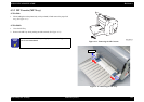
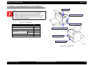
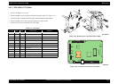
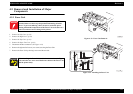
5. Disconnect all the connectors and flat cables on the Mechanical Control Board.
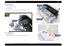
6. Remove the six screws, and remove the C533 Main.
(See Figure 4-22)
Figure 4-23. Removing the C533 Main (EPL-6200)
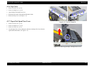
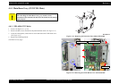
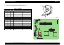
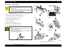
Figure 4-24. Connector Locations on C533 Main
Table 4-4. Connectors
CN No. Pins Color Connected to Remarks
403 21 –
Parallel I/F Board FFC
404 4 White
USB I/F Board
405 12 White
Control Panel
802 2 Blue
Fuser Unit
803 2 White
Paper Feed Solenoid
804 12 White
High Voltage Unit (CN1)
805 10 –
PH Unit FFC
806 4 White
Main Motor
807 7 Black
Power Supply Unit (CN2)
808 3 Black
Fuser Unit
809 5 White
PH Unit
810 2 White
Paper Jam Sensor
811 11 White
Lower Cassette Unit
812 3 Yellow
MP Tray Empty Sensor
813 3 White
Cooling Fan
815 10 White
Duplex Unit Connector
816 3 Blue
Cartridge Sensor