Chapter 4 FRU Removal Preparation 4-47
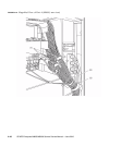
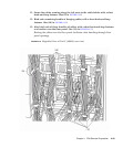
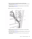
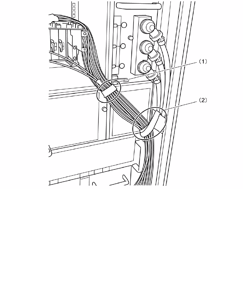
2. Bind the cables from the external I/O expansion unit with a short
hook-and-loop fastener while taking care not to touch the main line switch of
the ACS. (See (1) in
FIGURE 4-18.)
3. Fasten the cables with a short hook-and-loop fastener to the cable holder at
location (2) shown in
FIGURE 4-18.
FIGURE 4-18 Magnified View of Part A (M8000, rear view)
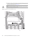
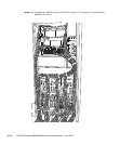
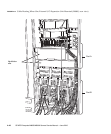
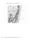
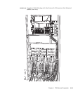
4. Fasten the cables with a short hook-and-loop fastener to the cable holder at
location (3) shown in
FIGURE 4-19.
5. Also bind the cables with a short hook-and-loop fastener at a location near the
floor panel. (See (4) in
FIGURE 4-19.)
Binding the cables near the floor panel facilitates cable handling through floor
panel openings.


