Chapter 12 Hard Disk Drive (HDD) Replacement 12-7
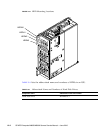
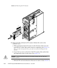
8. Remove the HDD unit to be replaced. (See FIGURE 12-2)
a. Press the square push button on the HDD unit to be replaced.
The eject/lock lever protrudes at an angle of about 45 degrees.
b. Pull the eject/lock lever to an angle of about 90 degrees to release the lock.
c. While grasping the eject/lock lever, pull out the HDD unit slowly from the
slot.
9. Place the removed HDD on an antistatic mat.
10. Mount the replacement HDD by following the removal instructions in Step 8 in
reverse order. Align the HDD with the slot guides, insert it carefully, and
secure it firmly.
Caution – Do not forcibly push the HDD when inserting it, even if it is not moving
smoothly. If the HDD is forcibly inserted despite the presence of any problem with a
connector pin, serious damage may result.
Do not insert an HDD into a slot while the eject/lock lever is closed. If an HDD is
inserted in this condition, it is stopped halfway and becomes difficult to pull out.
11. Switch on all main line switches for the AC section (ACS) in the power supply
system.
12. Confirm that the XSCF STANDBY LED (green) on the operator panel remains
lit. If it is blinking, wait until it remains lit.
13. Start (turn on power) all domains together. Take either of the following two
actions:
■ Press and hold down (for less than four seconds) the POWER switch on the
operator panel.
■ From a console that is connected to XSCF, execute the poweron -a command
of XSCF.
For details of the power-on operation, see Section 4.4.2, “Powering the Server On”
on page 4-19, and the SPARC Enterprise M3000/M4000/M5000/M8000/M9000
Servers XSCF User’s Guide.
14. Start the domain as necessary.
15. Restore the original mode switch setting on the operator panel.
Note – When the maintenance work is completed, be sure to confirm the mode
switch setting and return the switch to Locked.


