2-1
CHAPTER
2
Product Overview and
Troubleshooting
This chapter provides information that is required in troubleshooting.
This information is explained in the following sections:
■ Section 2.1, “System Views” on page 2-1
■ Section 2.2, “Labels” on page 2-11
■ Section 2.3, “Operator Panel” on page 2-16
■ Section 2.4, “Determining Which Diagnostics Methods To Use” on page 2-21
■ Section 2.5, “Checking the Server and System Configuration” on page 2-23
■ Section 2.6, “Error Conditions” on page 2-26
■ Section 2.7, “LED Error Display” on page 2-30
■ Section 2.8, “Using the Troubleshooting Commands” on page 2-34
■ Section 2.9, “Traditional Solaris Troubleshooting Commands” on page 2-37
2.1 System Views
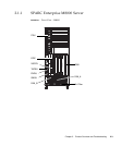
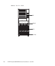
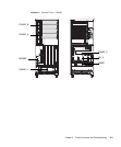
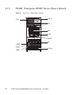
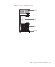
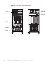
This section provides views of the high-end server. The figures can be used to locate
the component in the server to be subjected to maintenance.
In terms of its structure, the high-end server consists of a cabinet that includes
various mounted components and a front door, rear door, and side covers that
protect the mounted components. The side covers are removed when cabinets are
connected to each other or when the dual power feed option is connected to the
cabinet. The operator panel, which is mounted on the front door, is always
accessible. Each door can be locked with a key so that only the administrator can
open it.


