Chapter 6 Replacement of CPU/Memory Board Unit (CMU), CPU, and DIMM 6-37
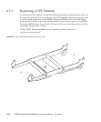
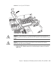
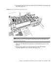
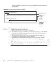
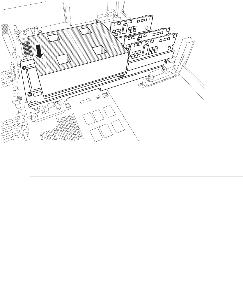
b. Fit the guide pin on the heat sink side of the CPU Module into the groove of
the CMU guide lock.
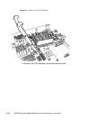
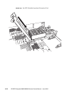
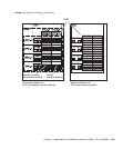
FIGURE 6-20 Set CPU Module on the Guide Lock (2)
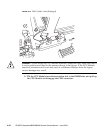
Note – Each CPU Module has two guide pins and two CMU guide locks on the
DDC side. Perform the work in such a way that both guide pins and both guide
locks are mounted correctly.
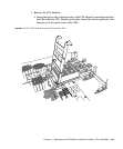
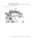
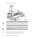
c. Move the CPU Module back and forth to confirm that the pins are in the
grooves.
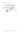
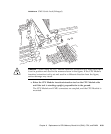
d. Fit the shorter guide pin on the insertion side of the CPU Module
insertion/extraction tool (A) into the CMU guide lock.


