Chapter 6 Replacement of CPU/Memory Board Unit (CMU), CPU, and DIMM 6-17
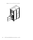
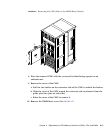
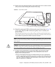
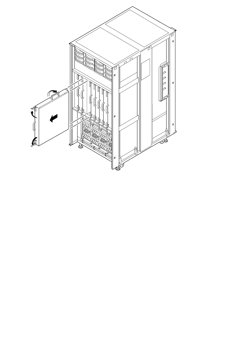
FIGURE 6-6 Removing the CMU (Rear of the M9000 Base Cabinet)
8. Place the removed CMU with the cover and its label facing upward on an
antistatic mat.
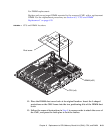
9. Remove the cover of the CMU.
a. Pull the two latches on the connector side of the CMU to unlock the latches.
b. Slide the cover of the CMU toward the connector side to release it from the
guide pins (two pins on each side).
c. Raise the cover of the CMU to remove it.
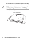
10. Remove the DIMM duct cover. (See
FIGURE 6-7)
1
1
2
3


