Replacing the control/LED board 65
5
After noting the position of the cable, disconnect the front panel cable
from the front panel connector on the system board (see “System board”
on page 6).
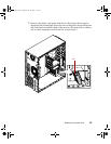
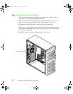
6 Remove the single screw securing the control/LED board to the chassis,
then disengage the alignment tabs from the chassis.
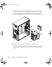
7 Remove the bottom drive cage. (See “To remove the front system fan:”
on page 58.)
8 Remove the control/LED board from the chassis.
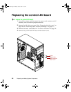
To install the new control/LED board:
1 Plug the front panel cable into the front panel connector on the system
board (see “System board” on page 6).
2 Insert the alignment tabs of the control/LED board into the slots on the
front of the chassis, then replace the retaining screw.
3 Replace the system fault LED reset switch button cover.
4 Replace the bezel, then close the case by following the instructions on
page 20.
5 Reconnect peripherals, the modem cord, and the power cord, then turn
on the system.
05032.book Page 65 Monday, July 10, 2000 11:43 AM


