


6-13
Q
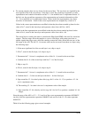
Graphically, the three segmentations could be represented as the following:
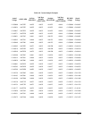
6.7:
Waveform
Samples
Log
Format
Q
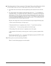
The Waveform Samples Log responds to High Speed Limit Triggers. It records samples from the
requested channels at the requested sample rate.
Q
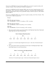
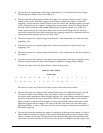
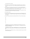
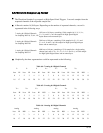
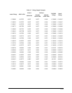
A Record contains 16,384 bytes. Depending on the number of requested channels, a record is
segmented in the following ways:
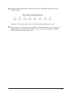
7 Analog & 8 Digital Channels
for Sampling Rate 16, 32, 64, 128
3 Analog & 8 Digital Channels
for Sampling Rate 256
1 Analog & 8 Digital Channels
for Sampling Rate 512
1024 sets of 16 bytes, containing 15-bit samples for I
A
, I
B
, I
C
, I
AUX
,
V
AN
, V
BN
and V
CN
, an 8-bit sample for High Speed Digital
Inputs States and an unused byte.
2048 sets of 8 bytes, containing 15-bit samples for V
AN
, V
BN
and
V
CN
or I
A
, I
B
and I
C
, an 8-bit sample for High Speed Digital Input
States and an unused byte.
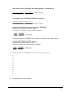
4096 sets of 4 bytes, containing a 15-bit sample for a single analog
channel (only one of V
AN
,V
BN
, V
CN
, I
A
, I
B
, I
C
and I
AUX
), an 8-bit sample
for High Speed Digital States and an unused byte.
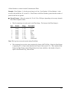
Table 6.6: 1 Analog & 8 Digital Channels
Low Hi
0123456789101112131415
16 17 18 19 20 21 22 23 24 25 26 27 28 29 30 31
HSI — Low Hi HSI — Low Hi HSI — Low Hi HSI –
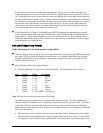
Table 6.4: 7 Analog & 8 Digital Channels
Low Hi Low Hi Low Hi Low Hi Low Hi Low Hi Low Hi HSI —
0123456789101112131415
16 17 18 19 20 21 22 23 24 25 26 27 28 29 30 31
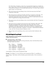
Table 6.5: 3 Analog & 8 Digital Channels
Low Hi Low Hi Low Hi Low Hi Low Hi Low Hi
0 1 2 3 4 5 6 7 8 9 10 11 12 13 14 15
HSI — HSI —
16 17 18 19 20 21 22 23 24 25 26 27 28 29 30 31
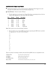
Analog Analog Analog Analog
V
AN
V
BN
V
CN
V
AN
V
BN
V
CN
I
A
I
B
I
C
I
AUX
V
AN
V
BN
V
CN