6-31
· The next 2 bytes indicate the desired state of the relay, in the same order as above. If the relay
is locked, as indicated in the previous 2 bytes, then the relay should be locked to this relay. If
the relay is unlocked, then this is the state in which the relay should be as indicated by the Relay
Logic Tree for this relay. A bit value of 0 indicates de-energized, or connected to Normal
Close; a bit value of 1 indicates energized, or connected to Normal Open.
· The next 2 bytes indicate that a command has begun to be sent to an external module to change
the state of a relay, in the same order as above.
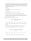
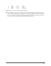
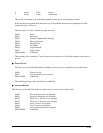
The first byte indicates to which relay the command is being sent:
0x000-0x003 Module 1, Relay 1-4
0x004-0x007 Module 2, Relay 1-4
0x008-0x00B Module 3, Relay 1-4
0x00C-0x00F Module 4, Relay 1-4
other No command sent
The second byte indicates whether the command being sent was to energize or de-energize the
relay. A value of 0x000 indicates the relay command was to de-energize the relay; any other
value indicates the command was to energize the relay.
· The last 2 bytes indicate successfully changed relay states, as recorded by the reception of the
response from the relay module, in the same order as above. A bit value of 0 indicates the relay
is de-energized, or connected to Normal Close; a bit value of 1 indicates the relay is energized,
or connect to Normal Open.
· The remaining 13 bytes are unused.
Q
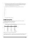
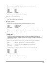
The normal sequence for a relay change would involve three records.
The first record would be a Stage 1 record. Stage 1 records are when the Relay Tree for an unlocked
relay has changed state for longer than the delay time for that Relay Tree, or when a command is
received over communication that locks or unlocks a relay.
The second record would be a Stage 2 record. Stage 2 records are recorded approximately with the
beginning of the transmission of the first byte of the command. Records of this type will report one and
only one relay command being issued at a time.
The third record would be a Stage 3 record. Stage 3 records are recorded when an acknowledgement for
a transmitted command to an external relay is received.
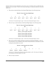
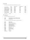
Should a problem occur with a response, multiple Stage 2 records can occur before a concluding Stage 3
record.
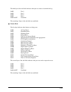
Should a Relay Logic Tree reverse itself, it might be possible to have two opposing Stage 1 records
without intervening or subsequent Stage 2 or 3 records, or to have a sequence of 1-2-1-3-2-3.


