


8-39
range from nominally 150V to 300V. Without identifiying this modification, it is necessary to add a
compensating Programmable Setting in to produce correct Secondary Voltage and Power. As a
Programmable Setting, however, end users could incorrectly enable or disable this feature. With this
setting, it is possible to have the adjustment automatically take place in the firmware. The following
codes are used to indicate this option:
0x000 Standard 150V Phase-to-Neutral Voltage
0x001 Special 300V Phase-to-Neutral Voltage
0x002-0x0FF Undefined, treated as 150 Phase-to-Neutral Voltage
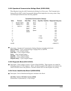
Sealing Switch (65365 High): Not all EPM units have the Sealing Switch security feature installed.
If installed, the end user can enable the security use of this switch and prevent changes to the
device’s Programmable Settings without physical, tamper-evident access to the unit. This
feature cannot be enabled if the switch is not installed; access is permanently denied. The following
codes are used to indicate this option:
0x000 No Sealing Switch
0x001 Sealing Switch Installed
0x002-0x0FF Undefined, treated as No Sealing Switch
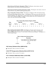
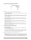
Memory (65365 Low): The amount of memory in the EPM 9800. The following codes are used to
indicate:
0x002 2048k NVRAM EPM 9800S
0x003 4096k NVRAM EPM 9800A
0x004-0x0FF Undefined, treated as 0k NVRAM
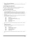
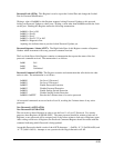
8.109: Flash Control Block (65409-65498)
Q
Description: Flash Control Registers included in this block:
GE Communicator EXT Operation Indicator (65409): When read, this byte reports which
Operation Mode is in use and why. If the value is 0x00000, then the Communication
Microcontroller is running in Normal Operation. Any non-zero value indicates that the
Communication Microcontroller is running in FLASH Operation. Each bit in the Register signals
the reason for being in FLASH Operation. The bits are:
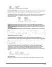
Bit 0: Checksum Failure in Code
Bit 1: Checksum Failure in Programmable Settings
Bit 2: Illegal Communication Settings in Programmable Settings
Bit 3: Forced FLASH Operation by Jumper
Bit 4: Requested FLASH Operation by Communication
Bit 5: Requested Default Communication Settings
Bit 6-15: Reserved, should be 0