


8-40
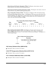
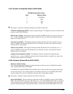
Bits 1, 4 and 5 indicate that all ports are set to the Default Communication Settings of Address 1,
Modbus RTU, 9600 Baud, 8 Data Bits, No Parity, 1 Stop Bit and No Delay.
Bit 2 indicates that one or more ports are set to an Illegal setting or combination of settings. In all
protocols, Baud Rate, Stop Bits and Parity must be in the allowed range of settings. In Modbus,
Addresses must be in the range of 1-247. In Modbus RTU, the Data Bits must be 8; in Modbus
ASCII, the Data Bits must be 7 or 8. In DNP, the Address must not be 0x0FFFF and the Data Bits
must be 8. If any of the above conditions are false, that port uses the Default Settings of Address 1,
Modbus RTU, 9600 Baud, 8 Data Bits, No Parity, 1 Stop Bit and No Delay. For forward
compatability, future protocols make no special demands on Address or Data Bits.
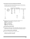
If a Modem (INP1) or Network (INP10) Option is installed, appropriate settings will be used for the
port for the use of the card, overriding any default that might occur due to other errors. Invalid
settings for the port would still cause Bit 2 to indicate a bad Programmable Setting.
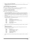
Communicator EXT FLASH Sequence & Status / FLASH Command (65410): When read, the
High byte is a sequence number and the Low byte is the status of the last FLASH action. After a
FLASH action is performed, the sequence number is incremented and the status of that action is
placed in the Status byte. If the sequence number did not increment, retry the action. Status values
are:
0x000 = Action Failed
0x001 = Action Passed
0x002 = Action Unfinished
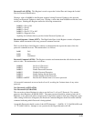
Resets to FLASH Operation initialize a 30-second Timeout. This Timeout is reset by a read by the
Locked Port of this Register (65410) or that of the DSP Microcontroller FLASH Sequence and
Status Register (65415). If this Timeout runs out, the Communication Microcontroller will reset.
When written, the Register initiates FLASH commands for the Communication Microcontroller
FLASH. Valid commands are:
0x00000 = Lock the FLASH Routines to this Com Port.
0x00001 = Erase the Code Blocks (0,1,2,3 and 5 (and 6 if Variation 0001)).
0x00002 = Calculate the Code Checksum (0,1,2,3 and 5 (and 6 if Variation 0001)).
0x00003 = Erase the Programmable Settings Block (7).
0x00004 = Calculate the Programmable Settings Checksum (7).
0x00100 = Reset to Normal Operation.
0x00101 = Reset to FLASH Operation, Programmed Communication Settings.
0x00102 = Reset to FLASH Operation, Default Communication Settings.
Locking the FLASH sets the Locked Port Register (65410) to the value for the port that sent the
Lock Command. Only the Locked Port can then reset the timer by reading the Status Registers
(65411 and 65415) or by writing to other Registers in the FLASH Blocks. Only the Locked Port
may send any of the other commands.
Checksum Calculations will update the appropriate Checksum Register for subsequent reads.