


6-29
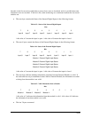
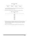
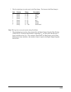
A bit value of 0 indicates that information for this relay is not yet valid; a bit value of 1
indicates that information for this relay is valid.
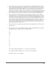
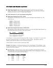
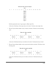
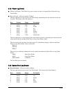
· The next 16 bytes represent the inputs to the Relay Logic Trees arranged as follows:
· Each bit represents the state of an input into a Relay Logic Tree. A bit value of 0 indicates a
false input value; a bit value of 1 indicates a true input value. These are the values for an input
before a possible NOT setting. If NOT is not set, the value remains the same. If NOT is set,
the value becomes the opposite.
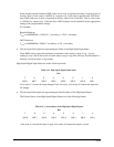
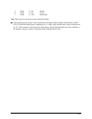
· The next 14 bytes represent the gate outputs of the Relay Logic Trees arranged as follows:
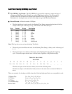
Table 6.16: Relay Valid Bits
Bits
059
33
Module 3Module 1 Module 2 Module 4
15 14 13 12 11 10 8 7 6 4 3 2 1
12 4123412 41234
Bits
Table 6.17: Relay Logic Tree Inputs
Input 2
Input 3
Input 4
Input 5
Input 6
Input 7
2 6 10 140 1 3 4 5 7 8 9 11 12 13 15
Input 1
Input 8