


Monitoring and Analyzing Switch Operation
Traffic Mirroring
2. On source switch A, configure an association between the remote mirror-
ing endpoint on switch C and a mirroring session on switch A (as
described in “3. Configure a Mirroring Session on the Source Switch” on
page B-52).
3. On switch A, configure a classifier-based mirroring policy to select
inbound TCP traffic destined to the server at 10.10.30.153, and apply the
policy to the interfaces of VLAN 10 (as described in “Selecting Inbound
Traffic Using Advanced Classifier-Based Mirroring” on page B-66).
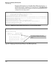
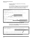
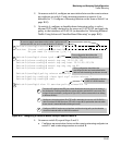
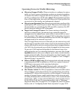
Switch-A(config)# mirror 1 remote ip 10.10.10.119 9300 10.10.30.2
Caution: Please configure destination switch first.
Do you want to continue [y/n]? y
Switch-A(config)# class ipv4 tcp7
Switch-A(class-config)# match tcp any 10.10.30.153
Switch-A(class-config)# match tcp any host 10.10.20.153/24
Switch-A(class-config)# match tcp any any eq 80
Switch-A(class-config)# exit
Switch-A(config)# policy mirror mirrorTCP
Switch-A(policy-config)# class ipv4 tcp7 action mirror 1
Switch-A(policy-config)# exit
Switch-A(config)# vlan 10 service-policy mirrorTCP in
Configures a class that selects IPv4 TCP traffic destined to: the server at 10.10.30.153, a
device in subnet 10.10.20.0, and any TCP traffic on port 80. (A packet that does not match
these criteria is transmitted without being mirrored.)
Configures VLAN 10 as the source interface, and the mirroring policy as the selection
criteria for inbound traffic on VLAN 10 in session 1.
The source IP address and UDP port number identify the mirroring source in session 1;
the destination IP address identifies the remote switch to which traffic is mirrored. (The
exit port for mirrored traffic, configured in Figure B-51, and the remote switch can belong
to different VLANs.)
1
2
3
Policy configuration that defines the
preconfigured class and session/destination
device to which matching packets are mirrored
Class configuration that defines the
matching TCP packets to be mirrored
On a source switch, associates session number 1 with a source IP
address and UDP port, and a remote destination IP address.
Policy application to inbound
traffic on a VLAN interface
1
2
3
Figure B-52. Configuring a Classifier-Based Policy on Source Switch A
4. On source switch B, repeat Steps 2 and 3:
a. Configure an association between the remote mirroring endpoint on
switch C and a mirroring session on switch B.
B-89