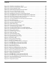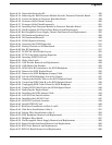
Figures
12
Figure 3-21. Disk Drive Installation in Slot 2 . . . . . . . . . . . . . . . . . . . . . . . . . . . . . . . . . . . . . . . . . . 86
Figure 3-22. Disk Drive Installation in Slots 1 and 2 . . . . . . . . . . . . . . . . . . . . . . . . . . . . . . . . . . . . 86
Figure 3-23. Extender Board Latches . . . . . . . . . . . . . . . . . . . . . . . . . . . . . . . . . . . . . . . . . . . . . . . . 89
Figure 3-24. Removing the Processor Extender Board . . . . . . . . . . . . . . . . . . . . . . . . . . . . . . . . . . . 90
Figure 3-25. Processor Cable Placed Correctly . . . . . . . . . . . . . . . . . . . . . . . . . . . . . . . . . . . . . . . . . 91
Figure 3-26. Processor Cable Placed Incorrectly . . . . . . . . . . . . . . . . . . . . . . . . . . . . . . . . . . . . . . . . 92
Figure 3-27. Installing the Processor on the Extender Board . . . . . . . . . . . . . . . . . . . . . . . . . . . . . . 93
Figure 3-28. 16-DIMM Memory Extender Board Minimum Configuration . . . . . . . . . . . . . . . . . . . 95
Figure 3-29. 32-DIMM Memory Extender Board Minimum Configuration . . . . . . . . . . . . . . . . . . . 97
Figure 3-30. Removing the Memory Extender Board . . . . . . . . . . . . . . . . . . . . . . . . . . . . . . . . . . . . 98
Figure 3-31. Inserting DIMM Into the Extender Board Connector . . . . . . . . . . . . . . . . . . . . . . . . . 99
Figure 3-32. Slot ID Numbering . . . . . . . . . . . . . . . . . . . . . . . . . . . . . . . . . . . . . . . . . . . . . . . . . . . . 101
Figure 3-33. PCI/PCI-X OLX Divider Layout . . . . . . . . . . . . . . . . . . . . . . . . . . . . . . . . . . . . . . . . . 104
Figure 3-34. Inserting PCI/PCI-X Card . . . . . . . . . . . . . . . . . . . . . . . . . . . . . . . . . . . . . . . . . . . . . . 105
Figure 3-35. Slider Gate Latch . . . . . . . . . . . . . . . . . . . . . . . . . . . . . . . . . . . . . . . . . . . . . . . . . . . . . 106
Figure 3-36. Removing the SCSI Jumper Cable . . . . . . . . . . . . . . . . . . . . . . . . . . . . . . . . . . . . . . . 111
Figure 3-37. Installing the Duplex Board . . . . . . . . . . . . . . . . . . . . . . . . . . . . . . . . . . . . . . . . . . . . 112
Figure 3-38. Installing SCSI Cable B to the SCSI Backplane . . . . . . . . . . . . . . . . . . . . . . . . . . . . 113
Figure 3-39. Installing SCSI Cable B to the SCSI Adapter Board. . . . . . . . . . . . . . . . . . . . . . . . . 114
Figure 3-40. Ports on Server Rear. . . . . . . . . . . . . . . . . . . . . . . . . . . . . . . . . . . . . . . . . . . . . . . . . . . 117
Figure 3-41. iLO MP Setup Flowchart . . . . . . . . . . . . . . . . . . . . . . . . . . . . . . . . . . . . . . . . . . . . . . . 120
Figure 3-42. Web Login Page . . . . . . . . . . . . . . . . . . . . . . . . . . . . . . . . . . . . . . . . . . . . . . . . . . . . . . 128
Figure 3-43. Status Summary Page . . . . . . . . . . . . . . . . . . . . . . . . . . . . . . . . . . . . . . . . . . . . . . . . . 129
Figure 3-44. Front Control Panel LEDs . . . . . . . . . . . . . . . . . . . . . . . . . . . . . . . . . . . . . . . . . . . . . . 140
Figure 3-45. QuickFind Diagnostic Panel. . . . . . . . . . . . . . . . . . . . . . . . . . . . . . . . . . . . . . . . . . . . . 143
Figure 5-1. PCI/PCI-X LEDs . . . . . . . . . . . . . . . . . . . . . . . . . . . . . . . . . . . . . . . . . . . . . . . . . . . . . . . 160
Figure 5-2. Front Control Panel LEDs . . . . . . . . . . . . . . . . . . . . . . . . . . . . . . . . . . . . . . . . . . . . . . . 162
Figure 5-3. QuickFind Diagnostic Panel. . . . . . . . . . . . . . . . . . . . . . . . . . . . . . . . . . . . . . . . . . . . . . 164
Figure 5-4. I/O Baseboard LEDs, Buttons, and Sensors . . . . . . . . . . . . . . . . . . . . . . . . . . . . . . . . . 165
Figure 5-5. 32-DIMM Memory Extender Board LEDs. . . . . . . . . . . . . . . . . . . . . . . . . . . . . . . . . . . 167
Figure 5-6. 16-DIMM Memory Extender Board LEDs. . . . . . . . . . . . . . . . . . . . . . . . . . . . . . . . . . . 168
Figure 6-1. Accessing T-25 Screws . . . . . . . . . . . . . . . . . . . . . . . . . . . . . . . . . . . . . . . . . . . . . . . . . . 177
Figure 6-2. Pedestal-Mounted Server . . . . . . . . . . . . . . . . . . . . . . . . . . . . . . . . . . . . . . . . . . . . . . . . 179
Figure 6-3. Removing and Replacing the Front Bezel . . . . . . . . . . . . . . . . . . . . . . . . . . . . . . . . . . . 180
Figure 6-4. Removing and Replacing the Front Cover . . . . . . . . . . . . . . . . . . . . . . . . . . . . . . . . . . 182
Figure 6-5. Removing and Replacing the Top Cover . . . . . . . . . . . . . . . . . . . . . . . . . . . . . . . . . . . . 183
Figure 6-6. Memory Extender Board Latches . . . . . . . . . . . . . . . . . . . . . . . . . . . . . . . . . . . . . . . . . 185
Figure 6-7. Memory Extender Board . . . . . . . . . . . . . . . . . . . . . . . . . . . . . . . . . . . . . . . . . . . . . . . . 186
Figure 6-8. 16-DIMM Memory Extender Board Slot IDs. . . . . . . . . . . . . . . . . . . . . . . . . . . . . . . . . 189
Figure 6-9. 32-DIMM Memory Extender Board Slot IDs. . . . . . . . . . . . . . . . . . . . . . . . . . . . . . . . . 190
Figure 6-10. Inserting DIMM into the Extender Board Connector . . . . . . . . . . . . . . . . . . . . . . . . 191
Figure 6-11. Processor Extender Board . . . . . . . . . . . . . . . . . . . . . . . . . . . . . . . . . . . . . . . . . . . . . . 193
Figure 6-12. Dipswitch Location. . . . . . . . . . . . . . . . . . . . . . . . . . . . . . . . . . . . . . . . . . . . . . . . . . . . 194


