


Chapter 6
Removing and Replacing Components
I/O Baseboard Assembly
206
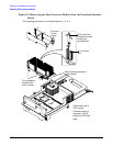
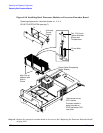
Replacing a Hot-Swappable Chassis Fan Unit
To replace a hot-swappable chassis fan unit, follow these steps:
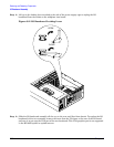
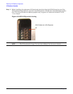
Step 1. Orient the fan unit by aligning the appropriate icon on the fan unit handle to the identical icon on
the chassis wall. Fan units 0 and 1 have “circle” icons and fan unit 2 has a “square” icon.
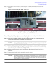
Step 2. Push the fan unit firmly into the housing and close the handle until flush to the top of the chassis.
The fan unit plugs into the power outlet on the I/O baseboard.
CAUTION If the fan unit handle does not close completely it is misaligned. Remove the fan unit
and check that the alignment icons are oriented correctly.
Step 3. Check the QuickFind diagnostic panel LED indicating the replaced fan unit.
• When the fan functions normally, the LED is off
• When the fan fails, the LED is lit
Step 4. Replace the top cover. (See “Replacing the Top Cover” on page 183.)
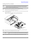
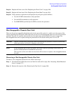
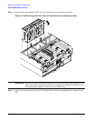
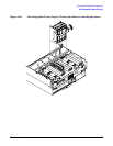
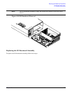
I/O Baseboard Assembly
System information is stored on the I/O baseboard assembly. If you are installing a new I/O baseboard
assembly, you must write the serial number and model string information to the I/O baseboard after
installation.
WARNING Ensure that the system is powered off and all power sources have been disconnected
from the server before removing or replacing the I/O baseboard assembly.
Voltages are present at various locations within the server whenever an ac power
source is connected. This voltage is present even when the main power switch is in
the off position.
Failure to observe this warning can result in personal injury or damage to
equipment.
CAUTION Failure to properly complete the steps in this procedure results in erratic system behavior or
system failure. For assistance with this procedure contact your local HP Authorized Service
Provider.
Observe all ESD safety precautions before attempting this procedure. Failure to follow ESD
safety precautions can result in damage to the server.