


Chapter 6
Removing and Replacing Components
Replacing Dual Processor Modules
196
Replacing Dual Processor Modules
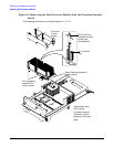
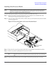
Dual processor modules are located on the top and bottom surfaces of the processor extender board.
WARNING Ensure that the system is powered off and all power sources have been disconnected
from the server before removing or replacing a processor.
Voltages are present at various locations within the server whenever an ac power
source is connected. This voltage is present even when the main power switch is in
the off position.
Failure to observe this warning can result in personal injury or damage to
equipment.
CAUTION Ensure that processor speed and cache size are identical for all processors. Failure to observe
this caution results in performance degradation or system failure.
The easiest way to ensure compatibility is to use dual processor modules with identical part
numbers.
Dual Processor Modules
HP 9000 rp4410 and rp4440 servers use dual processor modules. That is, each module contains two
processors. When only one processor is activated (a 1P/1C configuration of the HP 9000 rp4410 server), the
second processor is installed but not enabled and is available for future use.
• The HP 9000 rp4410 server may contain one or two dual processor modules to provide 1/1C, 1P/2C, or
2P/2C configurations.
• The HP 9000 rp4440 server can contain one, two, three, or four dual processor modules to provide 1P/2C,
2P/2C, 3P/2C, or 4P/2C configurations.
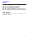
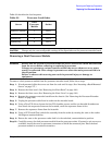
If fewer than the maximum number of dual processor modules are to be installed, the modules must be
installed in the appropriate connectors (see Table 6-3).
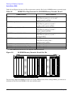
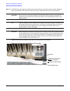
Processor Load Order
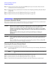
You can install up to four dual processor modules on the processor extender board, which is located under the
front cover in the top service bay, directly under the memory extender board. If fewer than the maximum
number of dual processor modules are to be installed (one in the HP 9000 rp4410 server or fewer than four in
the HP 9000 rp4440 server), they must be installed in the designated locations on the processor extender
board.
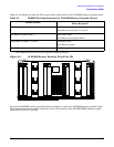
The connectors slots or sockets on the processor extender board are labeled CPU0 through CPU3. CPU0 and
CPU1 connectors are located on the top of the processor extender board and CPU2 and CPU3 connectors are
located on the bottom.