


Chapter 5
Troubleshooting
Troubleshooting Using LED Indicators
166
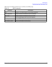
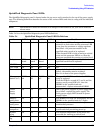
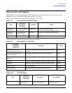
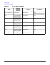
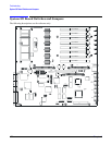
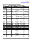
Table 5-5 lists the I/O baseboard LEDs, buttons, and sensors.
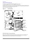
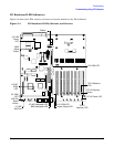
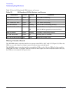
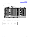
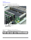
Memory Extender Boards
The 32-DIMM memory extender board has two power status LEDs, 1.25 V and 1.5 V (Figure 5-5). When the
LEDs are on, each respective voltage is present on the memory extender board.
The 16-DIMM memory extender board has one condition LED on each of the two VRMs. If either condition
VRM LED is on, there is a problem with that VRM. You must replace the entire extender board in this case;
the VRMs are not customer self-repair units.
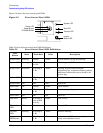
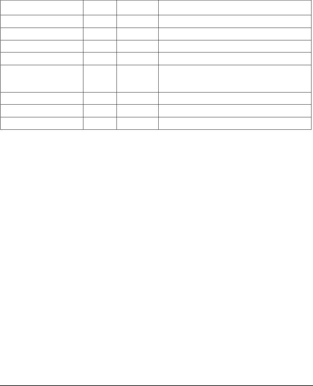
Table 5-5 I/O Baseboard LEDs, Buttons, and Sensors
LED/Button Color Status Condition
12V VRM Power LED Green On 12V VRM is functioning.
5V VRM Power LED Green On 5V VRM is functioning.
3.3V VRM Power LED Green On 3.3V VRM is functioning.
iLO MP heartbeat Green Blinking The iLO MP is functioning correctly.
iLO MP Self Test LED Amber On
Off
The iLO MP is executing the internal self test.
The iLO MP has passed the internal self test.
BMC Heartbeat Green Blinking The BMC is functioning correctly.
3.3 VSB Power LED Green On Standby power is available.
iLO MP Soft Reset Button N/A Press Resets the iLO MP values.