Monitoring and Operating the Controller
124 UDC2500 Universal Digital Controller Product Manual 4/07
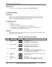
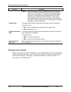
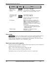
Function Press Result
Viewing the present
ramp or soak
segment number
and time
Lower
Display
Lower
Display
Lower
Display
until you see
Upper Display = PV value
Lower Display = XXHH.MM
Time remaining in the SEGMENT in hours and
minutes. XX = The current number, 1 to 12.
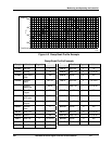
Viewing the number
of cycles left in the
program
Lower
Display
Lower
Display
Lower
Display
until you see
Upper Display = PV value
Lower Display = REC_XX
Number of cycles remaining in the setpoint
program. X = 0 to 99
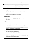
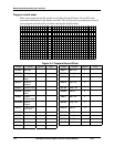
End Program
When the final segment is completed, the
“RUN” in the upper display either changes to
“HOLD” (if configured for HOLD state), or
disappears (if configured for disable of setpoint
programming).
• The controller either operates at the last
setpoint in the program or goes into manual
mode/failsafe output.
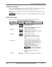
Disable Program See Section
3 – Configuration Group
“SPPROG” for details.
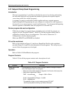
Power outage
ATTENTION If power is lost during a program, upon power-up the controller will be in
hold and the setpoint value will be the setpoint value prior to the beginning of the
setpoint program. The program is placed in hold at the beginning. The mode will be as
configured under “PWR UP” in the “CONTROL” group.
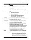
Digital input (remote switch) operation
Program can be placed in RUN or HOLD state through a remote dry contact connected to
optional digital input terminals, as follows:
RUN—contact closure places Program in RUN state, OR
HOLD—contact closure places Program in HOLD state
Opening the contact will cause the Controller to revert to its original state.


