


Configuration
4/07 UDC2500 Universal Digital Controller Product Manual 57
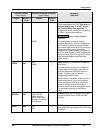
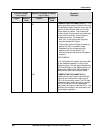
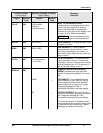
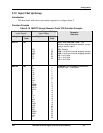
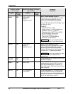
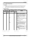
Function Prompt
Lower Display
Selection or Range of Setting
Upper Display
English Numeric
Code
English Numeric
Code
Parameter
Definition
IN1 LO 604
−999 to 9999
floating in
engineering units
INPUT 1 LOW RANGE VALUE in
engineering units is displayed for all inputs
but can only be configured for linear or
square root transmitter characterization.
Scale the #1 input signal to the display value
you want for 0 %. See example above.
ATTENTION The control setpoint will be
limited by the range of units selected here.
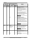
RATIO1 605
-20.0 to 20.0
RATIO ON INPUT 1—Select the Ratio value
you want on Input 1.
BIAS 1 606
-999 to 9999
BIAS ON INPUT 1 — Bias is used to
compensate the input for drift of an input
value due to deterioration of a sensor, or
some other cause. Select the bias value you
want on Input 1.
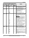
FILTR1 607
0 to 120 seconds
0 = No Filter
FILTER FOR INPUT 1—A software digital
filter is provided for Input 1 to smooth the
input signal. You can configure the first order
lag time constant from 1 to 120 seconds. If
you do not want filtering, enter 0.
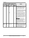
BRNOUT 608
BURNOUT PROTECTION (SENSOR
BREAK) provides most input types with
upscale or downscale protection if the input
fails.
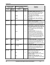
NONE
0
NO BURNOUT—Pre-configured Failsafe
output (selected in the CONTROL Set up
Group) applied if failed input is detected
(does not apply for an input out of range).
Diagnostic message IN1 FAIL is
intermittently flashed on the lower display.
UP
1
UPSCALE BURNOUT will force the Input 1
signal to the full scale value when the sensor
fails. Diagnostic message IN1 FAIL
intermittently flashed on the lower display.
The controller remains in Automatic control
mode and adjusts the controller output signal
in response to the full scale Input 1 signal
developed by the Burnout circuitry.