


Configuration
60 UDC2500 Universal Digital Controller Product Manual 4/07
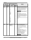
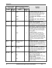
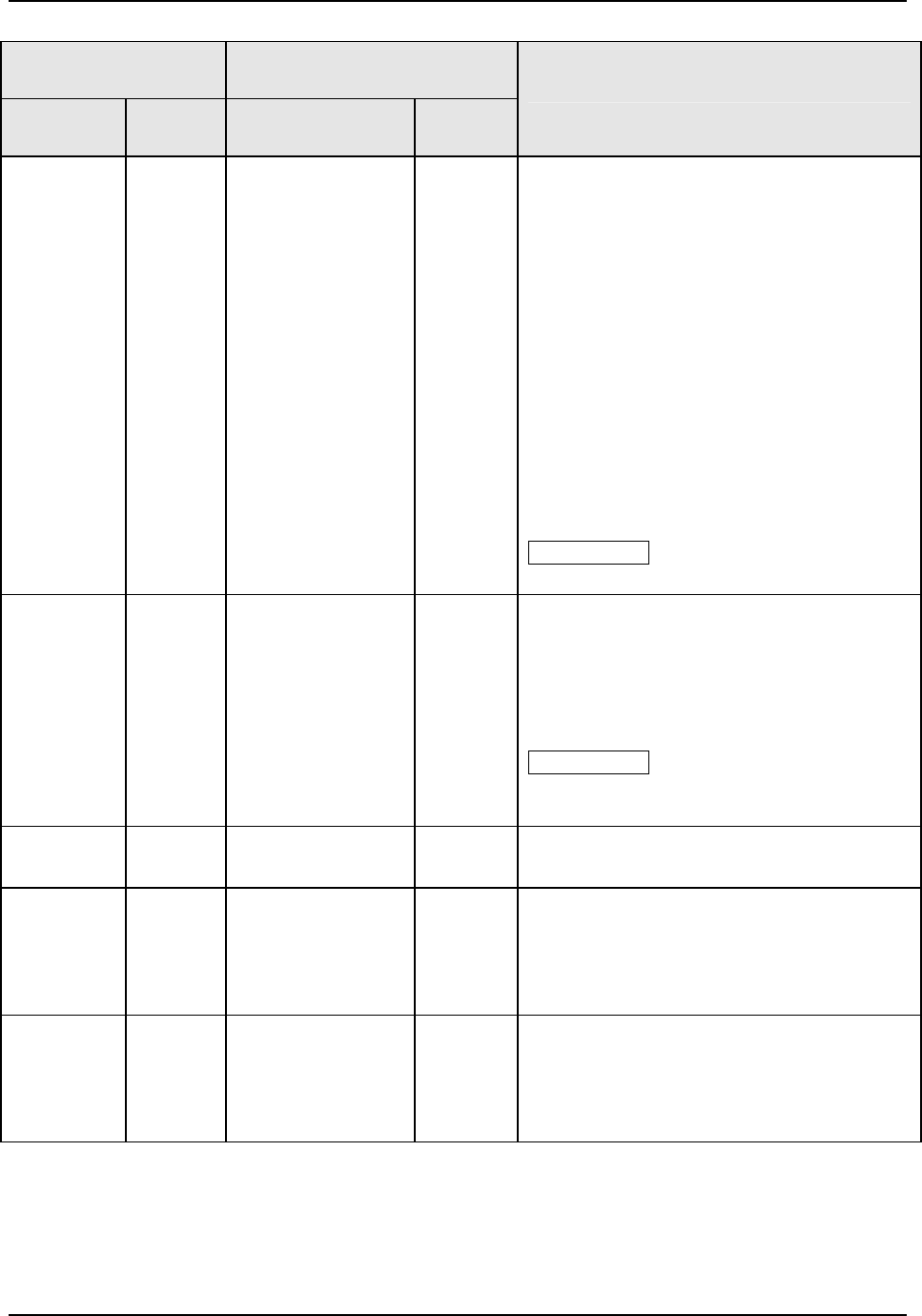
Function Prompt
Lower Display
Selection or Range of Setting
Upper Display
English Numeric
Code
English Numeric
Code
Parameter
Definition
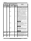
IN2 HI 703
−999 to 9999
floating in
engineering units
INPUT 2 HIGH RANGE VALUE in
engineering units is displayed for all inputs
but can only be configured for linear or
square root transmitter characterization.
Scale the #2 input signal to the display value
you want for 100 %.
EXAMPLE:
Process Variable = Flow
Range of Flow = 0 to 250 Liters/Minute
Actuation (Input 2) = 4 to 20 mA
Characterization (XMITTER) = LINEAR
Set IN1 HI display value to 250
Set IN1 LO display value to 0
Then 20 mA = 250 Liters/Minute
and 4 mA = 0 Liters/Minute
ATTENTION The control setpoint will be
limited by the range of units selected here.
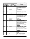
IN2 LO 704
−999 to 9999
floating in
engineering units
INPUT 2 LOW RANGE VALUE in
engineering units is displayed for all inputs
but can only be configured for linear or
square root transmitter characterization.
Scale the #2 input signal to the display value
you want for 0 %. See example above.
ATTENTION The control setpoint for Input
2 will be limited by the range of units
selected here.
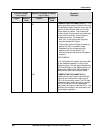
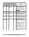
RATIO2 705
-20.0 to 20.0
RATIO ON INPUT 2—Select the Ratio value
you want on Input 2.
BIAS 2 706
-999 to 9999
BIAS ON INPUT 2 — Bias is used to
compensate the input for drift of an input
value due to deterioration of a sensor, or
some other cause. Select the bias value you
want on Input 2.
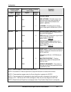
FILTR2 707
0 to 120 seconds
0 = No Filter
FILTER FOR INPUT 2—A software digital
filter is provided for Input 1 to smooth the
input signal. You can configure the first order
lag time constant from 1 to 120 seconds. If
you do not want filtering, enter 0.