


Modbus Read, Write and Override Parameters plus Exception Codes
4/07 UDC2500 Universal Digital Controller Product Manual 215
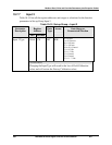
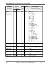
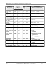
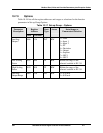
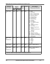
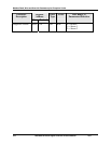
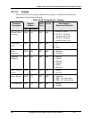
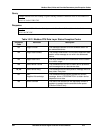
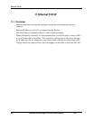
Parameter
Description
Register
Address
Data
Type
Access Data Range or
Enumerated Selection
Hex Decimal
Alarm 1 Setpoint 2
Type
008E 142 INT R/W Same as 140
Alarm 2 Setpoint 1
Type
0090 144 INT R/W Same as 140
Alarm 2 Setpoint 2
Type
0092 146 INT R/W Same as 140
Alarm 1 Setpoint 1
Event
008D 141 INT R/W 0 = Low Alarm
1 = High Alarm
Alarm 1 Setpoint 2
Event
008F 143 INT R/W 0 = Low Alarm
1 = High Alarm
Alarm 2 Setpoint 1
Event
0091 145 INT R/W 0 = Low Alarm
1 = High Alarm
Alarm 2 Setpoint 2
Event
0093 147 INT R/W 0 = Low Alarm
1 = High Alarm
Alarm Hysteresis 0029 041 FP R/W 0.0 to 100% of output or
span
Alarm Latching for
Output 1
00C8 200 INT R/W 0 = Non Latching
1 = Latching
Alarm States 00C9 201 INT R/W State = 0 = Not in Alarm
State = 1 = In Alarm
Bit 0 = Alarm 11 State
Bit 1 = Alarm 12 State
Bit 2 = Alarm 21 State
Bit 3 = Alarm 22 State
Event = 0 = Low
Event = 1 = High
Bit 4 = Alarm 11 Event
Bit 5 = Alarm 12 Event
Bit 6 = Alarm 21 Event
Bit 7 = Alarm 22 Event
Alarm 1 Blocking 00CA 202 INT R/W 0 = Disable
1 = Block 1
2 = Block 2
3 = Block 1 2