


Configuration
4/07 UDC2500 Universal Digital Controller Product Manual 81
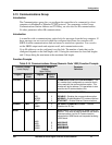
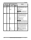
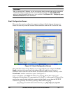
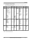
Function Prompt
Lower Display
Selection or Range of Setting
Upper Display
English Numeric
Code
English Numeric
Code
Parameter
Definition
ALARM1 1114
NO LAT
LATCH
0
1
LATCHING ALARM OUTPUT 1—Alarm
output 1 can be configured to be Latching or
Non-latching.
NO LAT—Non-latching
LATCH—Latching
ATTENTION When configured for latching,
the alarm will stay active after the alarm
condition ends until the RUN/HOLD key is
pressed.
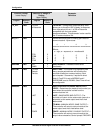
BLOCK 1115
DIS
AL1
AL 2
AL12
0
1
2
3
ALARM BLOCKING—Prevents nuisance
alarms when the controller is first powered
up. The alarm is suppressed until the
parameter gets to the non-alarm limit or
band. Alarm blocking affects both alarm
setpoints.
DISABLE—Disables blocking
AL1—Blocks alarm 1 only
AL2—Blocks alarm 2 only
AL12—Blocks both alarms
ATTENTION When enabled on power up
or initial enabling via configuration, the alarm
will not activate unless the parameter being
monitored has not been in an alarm condition
for a minimum of one control cycle (167 ms).
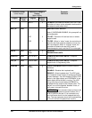
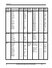
DIAGAL 1116
DIS
AL1
AL 2
DISWRN
0
1
2
3
DIAGNOSTIC—Monitors the Current Output
and/or Auxiliary Output for an open circuit
condition. If either of these two outputs falls
below about 3.5 mA, then an Alarm is
activated. This configuration is in addition to
whatever was selected for AxSxTYPE.
DISABLE—Disables Diagnostic Alarm
ALARM 1—Alarm 1 is diagnostic alarm
ALARM 2—Alarm 2 is diagnostic alarm
DISABLE WARNING—Disables Output Fail
message on lower display