


Installation
4/07 UDC2500 Universal Digital Controller Product Manual 21
selections, the Output 1 (HEAT) and Output 2 (COOL) signals will be present both on the
Auxiliary Output and on the two relays normally used for Time Duplex.
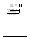
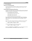
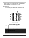
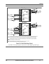
Wiring the Controller
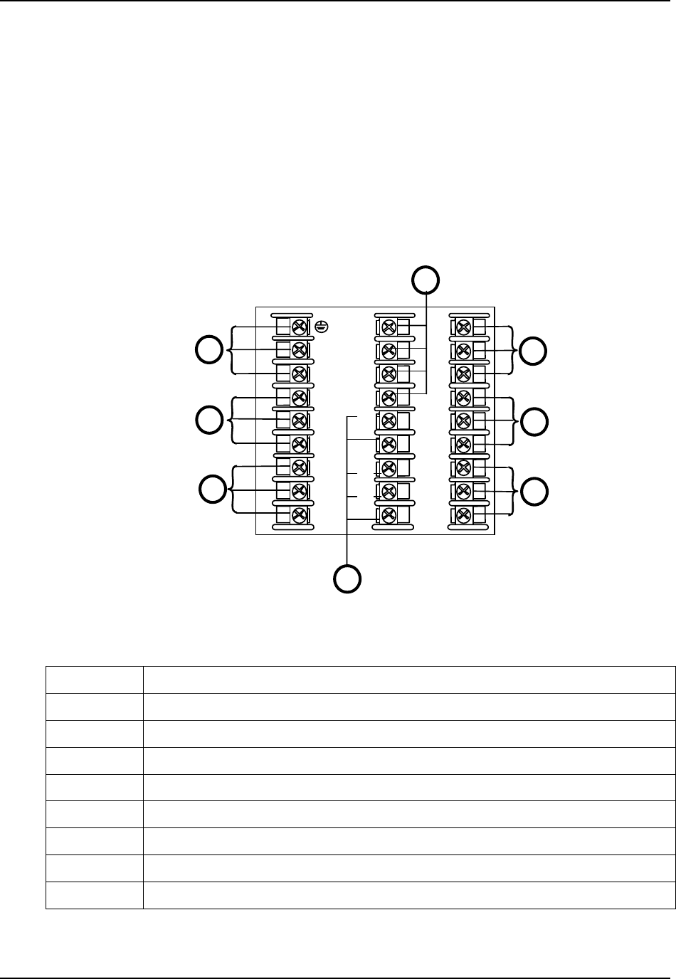
Using the information contained in the model number, select the appropriate wiring
diagrams from the composite wiring diagram below. Refer to the individual diagrams
listed to wire the controller according to your requirements.
L1
L2/N
4
5
6
7
1
10
11
12
13
14
15
16
17
7
8
9
20
21
22
23
24
25
26
27
18
19
See table for callout details
2
3
4
5
6
8
Figure 2-4 Composite Wiring Diagram
Callout Details
1 AC/DC Line Voltage Terminals. See Figure 2-5.
2 Output 3 Terminals. See Figure 2-8 through Figure 2-14.
3 Output 4 Terminals. See Figure 2-8 through Figure 2-14.
4 Outputs 1 and 2 Terminals. See Figure 2-8 through Figure 2-14.
5 Input #2 Terminals. See Figure 2-7.
6 Input #1 Terminals. See Figure 2-6.
7 Aux. Output and Digital Inputs Terminals. See Figure 2-17.
8 Communications Terminals. See Figure 2-15 and Figure 2-16.