


Configuration
4/07 UDC2500 Universal Digital Controller Product Manual 49
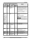
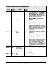
Function Prompt
Lower Display
Selection or Range of Setting
Upper Display
English Numeric
Code
English Numeric
Code
Parameter
Definition
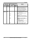
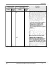
The actual slidewire position is then shown
on the lower display as POS. This value is
used for display only. It is NOT used in
the Three Position Step algorithm. To
configure this option, set Input 2 actuation to
SLIDEW. Calibrate the slidewire.
ATTENTION Other prompts affected:
DEADBD
NONE 5 This configuration is usually used for
Indicator applications. For this configuration,
the PV value is percent of range becomes
the control output value which is used by any
configured control output type. When
configured, the upper display shows the PV
while the lower display is blank unless more
than one analog input is configured, in which
case the lower display shows the other
analog inputs.
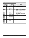
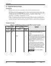
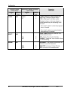
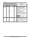
TIMER 402
DIS
ENAB
0
1
TIMER allows you to enable or disable the
timer option.
The timer option allows you to configure a
timeout period and to select timer start by
either the keyboard (RUN/HOLD key) or
Alarm 2. A digital input can also be
configured to start the timer.
When the timer is enabled, it has exclusive
control of the alarm 1 relay; any previous
alarm configuration is ignored. At timeout,
the timer is ready to be re-activated by
whatever action has been configured. Alarm
1 is activated at the end of the timeout
period.
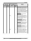
PERIOD 403
0:00 to 99:59
Select length of
time in Hours and
Minutes, or minutes
and seconds.
PERIOD allows you to configure the length
of timeout period (from 0 to 99 hours:59
minutes).
START 404
KEY
AL2
0
1
START allows you to select whether the
timer starts with the keyboard (Run/Hold key)
or Alarm 2.