


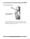
Modbus RTU Function Codes
4/07 UDC2500 Universal Digital Controller Product Manual 187
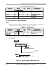
File Number
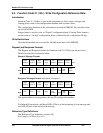
The file number word contains the register number from the register address structure
shown in Table 9-1 and Table 9-2. Although the register address structure tables indicate
up to 13 data registers are available for access, only register address 3 is currently
supported.
Register Address
The register address is used to designate the tag ID number for the parameter being
accessed. The register address is made up of two bytes—the MSB = 00 always. The LSB
contains the RS422 tag ID number. The tag ID numbers represent the parameter’s
register address(es). See Section 10 for the tag ID numbers.
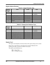
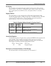
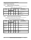
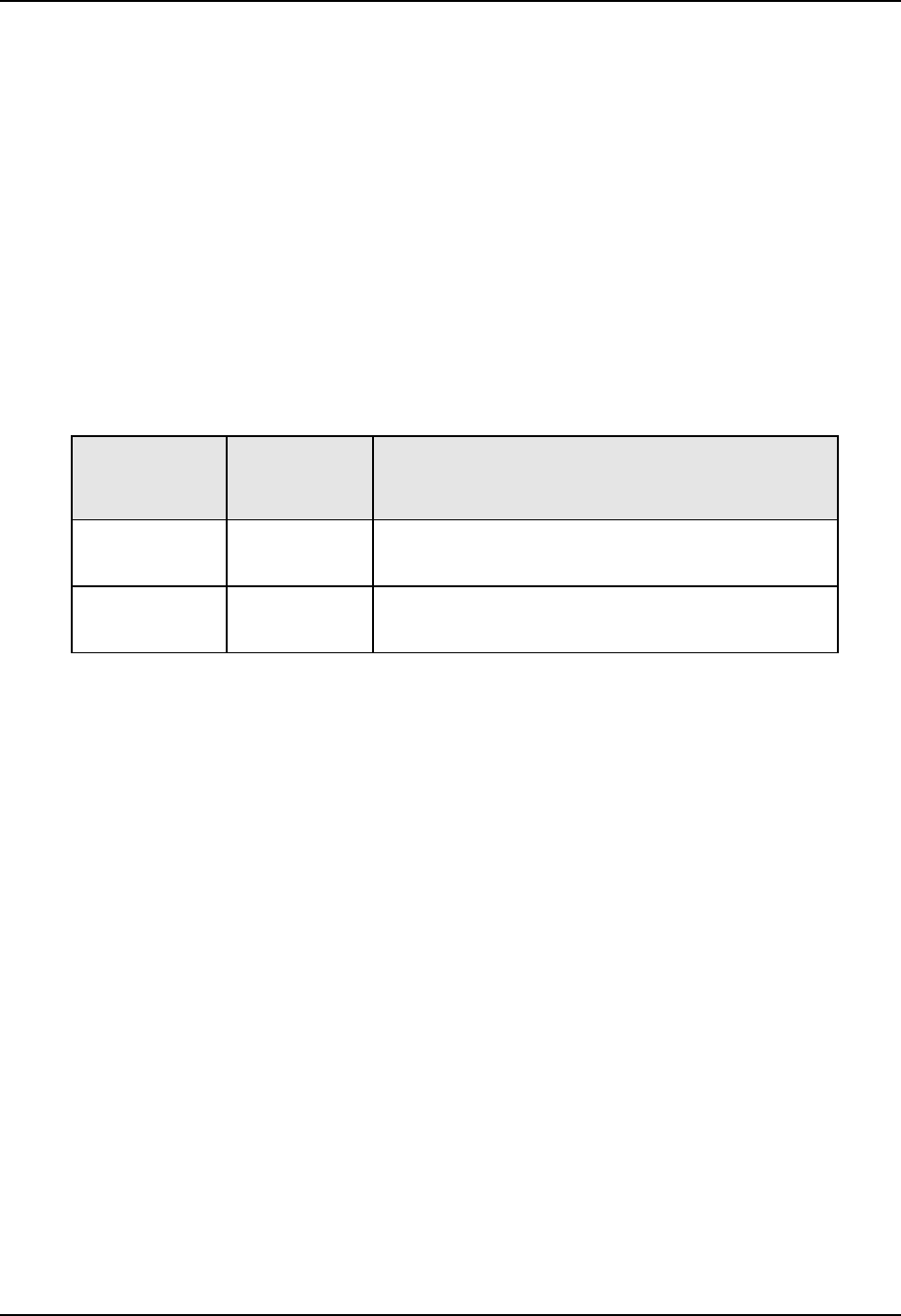
Table 9-4 Register Address Format for Function Code 21
Register
Address(es)
(Dec)
Register
Address(es)
(Hex)
Format
001 to 125 0001 to 007D analog formatted data
(2 registers – IEEE 32-bit floating point)
128 to 215
& 255
0080 to 00D7
& 00FF
integer formatted data
(2 registers – IEEE 32-bit floating point)
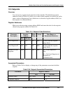
Unrestricted Registers
As mentioned previously, all register data is stored in the EEROM of this instrument with
some exceptions. These exceptions were made to allow write access to override
information. The registers, which are designated as Override values, are listed below.
These registers do not have restrictions on the number of writes.
ID Tag Register Number UDC Usage
125 (7Dh) Computer Setpoint
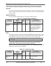
Restrictions on Parameter Numbers in One Message
The maximum number of writeable parameters per write request is 1.