


Configuration
58 UDC2500 Universal Digital Controller Product Manual 4/07
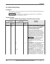
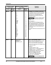
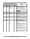
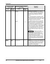
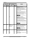
Function Prompt
Lower Display
Selection or Range of Setting
Upper Display
English Numeric
Code
English Numeric
Code
Parameter
Definition
DOWN
2
DOWNSCALE BURNOUT will force the
Input 1 signal to the lower range value when
the sensor fails. Diagnostic message IN1
FAIL intermittently flashed on the lower
display.
The controller remains in Automatic control
mode and adjusts the controller output signal
in response to the lower range Input 1 signal
developed by the Burnout circuitry.
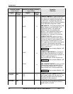
NOFS
3
This selection does not provide input failure
detection and should only be used when a
thermocouple input is connected to another
instrument which supplies the Burnout
current. (For this selection, no burnout signal
is sent to the sensor.) when a thermocouple
input is connected to another instrument
which supplies the Burnout current. (For this
selection, no burnout signal is sent to the
sensor.)
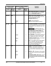
ATTENTION For Burnout to function
properly on a 0-20 mA input type (or a 0-5V
type that uses a dropping resistor), the
dropping resistor must be remotely located
(across the transmitter terminals).
Otherwise, the input at the UDC terminals
will always be 0 mA (i.e., within the normal
operating range) when the 0-20 mA line is
opened.
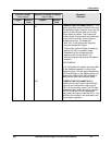
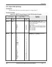
EMISS 609
0.01 to 1.00
EMISSIVITY is a correction factor applied to
the Radiamatic input signal that is the ratio of
the actual energy emitted from the target to
the energy which would be emitted if the
target were a perfect radiator.
Available only for Radiamatic inputs.