


Introduction
4/07 UDC2500 Universal Digital Controller Product Manual 3
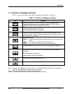
1.2 Function of Displays and Keys
Table 1-1 shows each key on the operator interface and defines its function.
Table 1-1Function of Displays and Keys
Key Function
SetupSetup
• Places the controller in the Configuration Set Up group select mode.
Sequentially displays Set Up groups and allows the FUNCTION key to
display individual functions in each Set Up group.
FunctionFunctionFunction
• Used in conjunction with the SET UP key to select the individual functions of
a selected Configuration Set Up group.
• Used during field calibration procedure.
Lower
Display
Lower
Display
Lower
Display
• Selects an operating parameter to be shown in the lower display. See
Section
4.5.2 for a list of the operating parameters and Section 4.5.3 for a list
of the diagnostic messages.
M-A
Reset
M-A
Reset
M-A
Reset
• Alternately selects:
AUTO Lower display automatically displays setpoint value in engineering
units.
MAN Lower display automatically indicates output in %.
RESET Only used on Limit Controllers to reset the Limit Relay.
SP
Select
SP
Select
SP
Select
• Setpoint Select Hold key down to cycle through configured setpoints.
Run
Hold
Run
Hold
Run
Hold
• Alternate action switch initiates or holds the Setpoint Ramp or Setpoint
Program.
• Acknowledges a latched alarm 1.
• Acknowledges Diagnostic Messages.
• Increases the selected parameter value.
• Decreases the selected parameter value.
Note 1: Value can be changed if in manual mode. For Three Position Step Control when a slidewire is
not used, the output value is the estimated motor position.
Note 2: Value can be changed via increment/decrement keys.
Note 3: The selected set can be changed via increment/decrement keys.