Installation
4/07 UDC2500 Universal Digital Controller Product Manual 9
Specifications
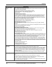
Controller Output
Types
Electromechanical Relays (One or Two)
SPDT contacts. Both Normally Open and Normally Closed contacts are brought out to the
rear terminals. Internally socketed.
Resistive Load: 5 amps @ 120 Vac or 240 Vac or 30 Vdc
Inductive Load (cos
ϕ
= 0.4): 3 amps @ 130 Vac or 250 Vac
Inductive Load (L/R = 7 msec): 3.5 amps @ 30 Vdc
Motor: 1/6 H.P.
Dual Electromechanical Relays
Two SPST contacts. One Normally Closed contact for each relay is brought out to the rear
terminals. Useful for Time Duplex or Three Position Step control applications, this option
takes the place of one of the above electromechanical relays, thus saving it for use as an
alarm. Units with this output option may have two additional relays (total of four relays) plus
the Second Current Output. Relays are internally socketed.
Resistive Load: 2 amps @ 120 Vac, 240 Vac or 30 Vdc
Inductive Load (cos
ϕ
= 0.4): 1 amp @ 130 Vac or 250 Vac
Inductive Load (L/R = 7 msec): 1 amp @ 30 Vdc
Solid State Relays (One or Two)
Zero-crossing type SPST solid state contacts consisting of a triac N.O. output. Internally
socketed.
Resistive Load: 1.0 amp @ 25°C and 120 or 240 Vac, 0.5 amp @ 55°C and 120 or 240 Vac
Inductive Load: 50 VA @ 120 Vac or 240 Vac
Minimum Load: 20 milliamps
Open Collector Outputs (One or Two)
Socketed assembly replacing a relay. Opto-isolated from all other circuits except current
output and not from each other. Internally powered @ 30 Vdc.
Note: Applying an external power supply to this output will damage the instrument.
Maximum Sink Current: 20 mA
Short-circuit current limit: 100 mA
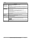
Current Outputs (One or Two)
These outputs provide a 21 mA dc maximum into a negative or positive grounded load or into
a non-grounded load. Current outputs are isolated from each other, line power, earth ground
and all inputs. Outputs can be easily configured via the keyboard for either direct or reverse
action and for either 0 to 20 mA or 4 to 20 mA without field calibration.
The second current output can be used in an Auxiliary Output mode. This Auxiliary Output
can be configured to represent either Input, PV, Setpoint, Deviation, or Control output. The
range of an Auxiliary Output can be scaled per the range of the selected variable and can be
set anywhere between 0 to 21 mA. The Second Current Output is mutually exclusive with the
second Digital Input.
Resolution: 12 bits over 0 to 21 mA
Accuracy: 0.05% of full scale
Temperature Stability: 0.01% F.S./°C
Load Resistance: 0 to 1000 ohms
Alarm Outputs
(Optional)
One SPDT Electromechanical relay. A second alarm is available if the second control relay
is not used for control purposes or when the Dual Relay Option is used.
Up to four setpoints are independently set as high or low alarm, two for each relay. Setpoint
can be on any Input, Process Variable, Deviation, Manual Mode, Failsafe, PV Rate, RSP
Mode, Communication Shed, or Output. A single adjustable hysteresis of 0.0 to 100.0% is
provided. The alarm can also be set as an ON or OFF event at the beginning of a Setpoint
ramp/soak segment.
Alarm Relay Contacts Rating: Resistive Load: 5 amps at 120 Vac or 240 Vac or 30 Vdc
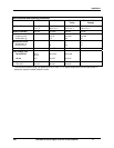
Isolation (Functional)
Analog Inputs: are isolated from all other circuits at 850Vdc for 2 seconds, but not from each
other.
Analog Outputs: are isolated from all other circuits at 850Vdc for 2 seconds.
AC Power: is electrically isolated from all other inputs and outputs to withstand a HIPOT
potential of 1900Vdc for 2 seconds per Annex K of EN61010-1.
Relay Contacts: with a working voltage of 115/230 Vac, are isolated from each other and all
other circuits at 345Vdc for 2 seconds.


