


Monitoring and Operating the Controller
128 UDC2500 Universal Digital Controller Product Manual 4/07
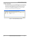
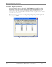
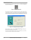
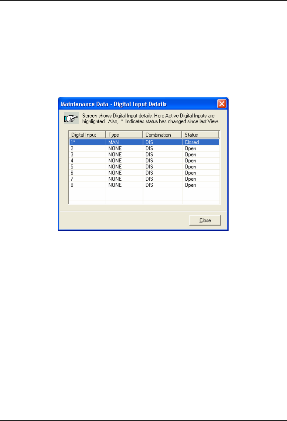
Loop Data – Digital Input Details
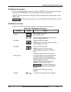
This screen appears when you click on the Digital Inputs button on the Loop Data
Maintenance Screen and shows the status of each Digital Input. NONE in the Type
column indicates that the Digital Input is disabled. Highlighted Digital Inputs are
currently active. An asterisk (*) indicates that the alarm has changed state since the last
communications transaction.
This instrument has a maximum of two Digital Inputs. Digital Inputs 3 through 8 will
always appear as NONE.
Figure 4-8 Digital Input Details Screen