


Troubleshooting/Service
162 UDC2500 Universal Digital Controller Product Manual 4/07
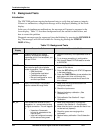
7.5 Background Tests
Introduction
The UDC2500 performs ongoing background tests to verify data and memory integrity.
If there is a malfunction, a diagnostic message will be displayed (blinking) in the lower
display.
In the case of simultaneous malfunctions, the messages will appear in sequence in the
lower display. Table 7-3 lists these background tests, the reason for their failure, and
how to correct the problem.
Diagnostic messages may be suppressed (stop the blinking) by pressing the RUN/HOLD
key. The messages will still be available for viewing by pressing the LOWER
DISPLAY key.
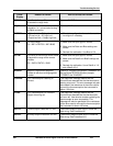
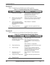
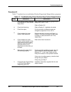
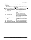
Table 7-3 Background Tests
Lower
Display
Reason for Failure How to Correct the Problem
E FAIL
Unable to write to non-volatile
memory. Anytime you change a
parameter and it is not accepted, you
will see E FAIL.
1. Check the accuracy of the parameter and re-
enter.
2. Try to change something in configuration.
3. Run through Read STATUS tests to re-write
to EEPROM.
FAILSF
This error message shows whenever
the controller goes into a failsafe
mode of operation. This will happen if:
• RAM test failed
• Configuration test failed
• Calibration test failed
• Burnout configured for none
and the input failed.
1. Run through STATUS check to determine the
reason for the failure.
2. Press the SET UP key until STATUS appears
in the lower display.
3. Press the FUNCTION key to see whether the
tests pass or fail, then run through the
STATUS codes a second time to see if the
error cleared.
IN1RNG
Input 1 out of range. The process
input is outside the range limits.
1. Make sure the range and actuation are
configured properly.
2. Check the input source.
3. Restore the factory calibration.
(See
Subsection
0.)
4. Field calibrate. See
Section 5 - Input
Calibration.
IN1_FL
Two consecutive failures of input 1
integration; i.e., cannot make analog
to digital conversion. This will happen
if:
• Upscale or Downscale
burnout is selected and the
input is open
• Input not configured correctly
for the sensor being used
1. Make sure the actuation is configured
correctly. See
Section 3 - Configuration.
2. Make sure the input is correct and that it has
not burned-out (opened).
3. Check for gross over-ranging with a
multimeter.
4. Restore factory calibration. See
Subsection
5.8