Configuration
76 UDC2500 Universal Digital Controller Product Manual 4/07
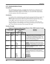
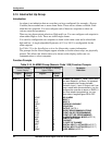
3.14 Alarms Set Up Group
Introduction
An alarm is an indication that an event that you have configured (for example—Process
Variable) has exceeded one or more alarm limits. There are two alarms available. Each
alarm has two setpoints. You can configure each of these two setpoints to alarm on
various controller parameters.
There are two alarm output selections, High and Low. You can configure each setpoint to
alarm either High or Low. These are called single alarms.
You can also configure the two setpoints to alarm on the same event and to alarm both
high and low. A single adjustable Hysteresis of 0 % to 100 % is configurable for the
alarm setpoint.
See Table 2-3 in the Installation section for Alarm relay contact information.
The prompts for the Alarm Outputs appear whether or not the alarm relays are physically
present. This allows the Alarm status to be shown on the display and/or sent via
communications to a host computer.
Function Prompts
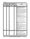
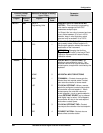
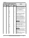
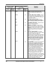
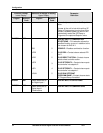
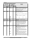
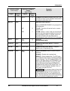
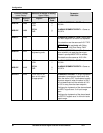
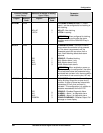
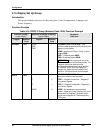
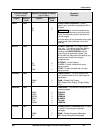
Table 3-15 ALARMS Group (Numeric Code 1100) Function Prompts
Function Prompt
Lower Display
Selection or Range of Setting
Upper Display
English Numeric
Code
English Numeric
Code
Parameter
Definition
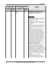
A1S1TY 1101
NONE
IN 1
IN 2
PROC
DE
OUT
SHED
E-ON
E-OF
MAN
RSP
FSAF
PrRT
DI 1
DI 2
BRAK
0
1
2
3
4
5
6
7
8
9
10
11
12
13
14
15
ALARM 1 SETPOINT 1 TYPE—Select what
you want Setpoint 1 of Alarm 1 to represent.
It can represent the Process Variable,
Deviation, Input 1, Input 2, Output, and if you
have a model with communications, you can
configure the controller to alarm on SHED. If
you have setpoint programming, you can
alarm when a segment goes ON or OFF.
NO ALARM
INPUT 1
INPUT 2
PROCESS VARIABLE
DEVIATION
OUTPUT (NOTE 1)
SHED FROM COMMUNICATIONS
EVENT ON (SP PROGRAMMING)
EVENT OFF (SP PROGRAMMING)
ALARM ON MANUAL MODE (NOTE 2)
REMOTE SETPOINT
FAILSAFE
PV RATE OF CHANGE
DIGITAL INPUT 1 ACTUATED (NOTE 7)
DIGITAL INPUT 2 ACTUATED (NOTE 7)
LOOP BREAK (NOTE 4)


