


Troubleshooting/Service
4/07 UDC2500 Universal Digital Controller Product Manual 163
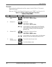
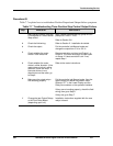
Lower
Display
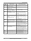
Reason for Failure How to Correct the Problem
IN2RNG
Input 2 out of range. The remote input
is outside the range limits.
Same as IN1RNG above.
IN2_FL
Two consecutive failures of input 2
integration. i.e., cannot make analog
to digital conversion.
Same as IN1FL above.
CNFERR
• PV low limit is > PV high limit
• SP low limit is > SP high limit
• Output low limit > Output high limit
1. Check the configuration for each item and
reconfigure if necessary.
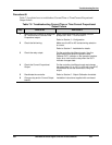
PV LIM
PV out of range.
PV = INP1 x RATIO1+ INP1 BIAS
1. Make sure the input signal is correct.
2. Make sure the Ratio and Bias settings are
correct.
3. Recheck the calibration. Use Bias of 0.0
RV LIM
The result of the formula shown below
is beyond the range of the remote
variable.
RV = INP2 X RATIO + BIAS
1. Make sure the input signal is correct.
2. Make sure the Ratio2 and Bias2 settings are
correct.
3. Recheck the calibration. Use a Ratio2 of 1.0
and a Bias2 of 0.0.
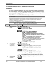
SEGERR
Setpoint Program start segment
number is less than ending segment
number.
Check SP Program configuration, subsection
3.5
Set up Group SPPROG function prompts
“STRSEG” and “ENDSEG”.
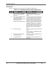
TCWARN
The Thermocouple is starting to
burnout.
This diagnostic message means that the
controller has detected that the thermocouple is
starting to burnout. This error message may also
be created if the resistance of the wires used to
connect the thermocouple to the instrument is
above 100 ohms.
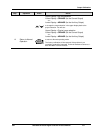
TCFAIL
The Thermocouple is in imminent
danger of burning out.
This diagnostic message means that the
controller has detected that the thermocouple
will soon fail. User should consider replacing the
thermocouple as soon as possible. This
message will also be generated if the resistance
of the wires used to connect the thermocouple to
the instrument is above 180 ohms.
OUT1FL
Current Output is less than 3.5 mA. The current output is open circuit. Check the
field wiring. See Procedure #2.
OUT2FL
Auxiliary Output is less than 3.5 mA. The auxiliary output is open circuit. Check the
field wiring. See Procedure #10.