


Modbus Read, Write and Override Parameters plus Exception Codes
204 UDC2500 Universal Digital Controller Product Manual 4/07
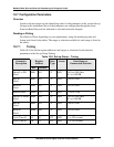
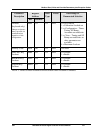
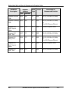
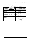
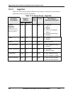
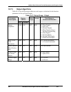
10.7.6 Input 1
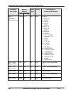
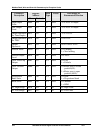
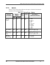
Table 10-14 lists all the register addresses and ranges or selections for the function
parameters in Set-up Group Input 1.
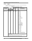
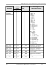
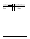
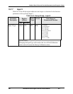
Table 10-14 Set-up Group – Input 1
Parameter
Description
Register
Address
Data
Type
Access Data Range or
Enumerated Selection
Hex Decimal
Input 1 Type 00A8 168 INT R/W
1 = B TC
2 = E TC H
3 = E TC L
4 = J TC H
5 = J TC M
6 = J TC L
7 = K TC H
8 = K TC M
9 = K TC L
10 = NNM H
11 = NNM L
12 = Nicrosil H TC
13 = Nicrosil L TC
14 = R TC
15 = S TC
16 = T TC H
17 = T TC L
18 = W TC H
19 = W TC L
20 = 100 PT RTD
21 = 100 PT LO RTD
22 = 200 PT RTD
23 = 500 PT RTD
24 = Radiamatic RH
25 = Radiamatic RI
26 = 0-20 mA
27 = 4-20 mA
28 = 0-10 mV
29 = 0-50 mV
30 = 100 mV
31 = 0-5 Vdc
32 = 1-5 Vdc
33 = 0-10 Vdc
34 = Unused
35 = Unused
36 = Thermocouple Differential
37 = PR40-PR20 Thermocouple
ATTENTION
Changing the Input Type will result in the loss of Field Calibration
values and will restore the Factory Calibration values.