


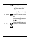
Input Calibration
4/07 UDC2500 Universal Digital Controller Product Manual 141
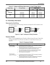
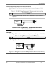
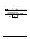
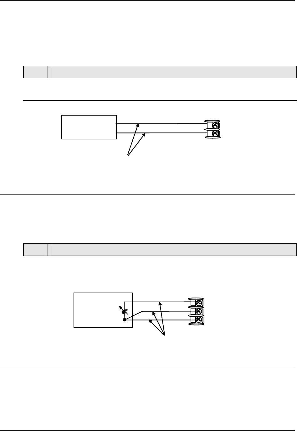
Thermocouple Inputs Using a Thermocouple Source
Refer to Figure 5-3 and wire the controller according to the procedure given in Table
5-5..
Table 5-5 Set Up Wiring Procedure for Thermocouple Inputs using
Thermocouple Source
Step Action
1
Connect the thermocouple extension wires to the terminals for Input #1 as shown in
Figure 5-3.
Thermocouple
Source
Thermocouple
Extension Wire
+
_
26
27
+
_
Thermocouple
Source
Thermocouple
Extension Wire
+
_
26
27
+
_
Figure 5-3 Wiring Connections for Thermocouple Inputs Using
Thermocouple Source
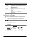
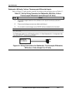
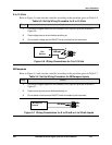
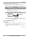
RTD Inputs
Refer to Figure 5-4 and wire the controller according to the procedure given in Table 5-6.
Table 5-6 Set Up Wiring Procedure for RTD Inputs
Step Action
1
Connect the copper leads from the calibrator to the Input #1 terminals as shown in
Figure 5-4.
Decade
Resistance
Box
25R
26+
27-
Copper Leads
Equal Length
Decade
Resistance
Box
25R
26+
27-
Copper Leads
Equal Length
Figure 5-4 Wiring Connections for RTD (Resistance Thermometer Device)