


Input Calibration
4/07 UDC2500 Universal Digital Controller Product Manual 143
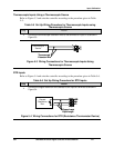
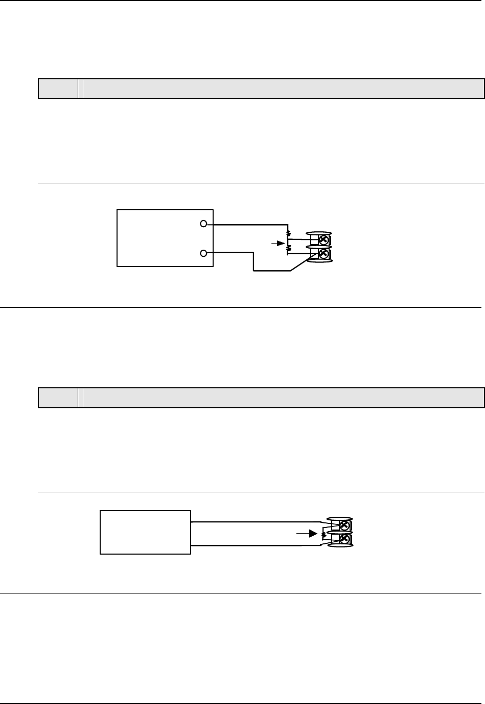
0 to 10 Volts
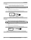
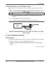
Refer to Figure 5-6 and wire the controller according to the procedure given in Table 5-8.
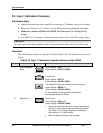
Table 5-8 Set Up Wiring Procedure for 0 to 10 Volts
Step Action
1
Connect the copper leads from the calibrator to the Input #1 terminals as shown in
Figure 5-6.
2
Place voltage source at zero before switching on.
3
Do not switch voltage source ON/OFF while connected to the instrument.
Volt
Source
_
+
1
2
3
100K pair
26+
27-
Volt
Source
_
+
1
2
3
100K pair
26+
27-
Figure 5-6 Wiring Connections for 0 to 10 Volts
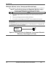
Milliamperes
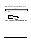
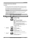
Refer to Figure 5-5 and wire the controller according to the procedure given in Table 5-7.
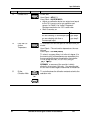
Table 5-9 Set Up Wiring Procedure for Milliampere Inputs
Step Action
1
Connect the copper leads from the calibrator to the Input #1 terminals as shown in
Figure 5-7.
2
Place current source at zero before switching on.
3
Do not switch current source ON/OFF while connected to the instrument.
Milliampere
Source
26+
27-
+
_
250 ohms
Milliampere
Source
26+
27-
+
_
250 ohms
Figure 5-7 Wiring Connections for 0 to 20 mA or 4 to 20 mA Inputs