


10 Intel NetStructure
®
MPCBL0001 High Performance Single Board Computer
Technical Product Specification
Contents
Figures
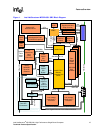
1 Intel NetStructure® MPCBL0001 SBC Block Diagram............................................................... 15
2 Memory Ordering........................................................................................................................20
3 Hardware Management Block Diagram......................................................................................27
4 IPMC Firmware Code Process ................................................................................................... 45
5 Upgrade via Remote Management Node ...................................................................................46
6 Hot-Swap Process...................................................................................................................... 51
7 Interrupt Signals .........................................................................................................................54
8 Power Good Map........................................................................................................................59
9 Reset Chain................................................................................................................................61
10 Watchdog Timers ....................................................................................................................... 62
11 Flow Diagram for Graceful Reboot Command ........................................................................... 68
12 Diagnostic Interrupt Command Implementation ......................................................................... 69
13 MPCBL0001 SBC Connector Locations.....................................................................................70
14 MPCBL0001NXX SBC Front Panel............................................................................................71
15 MPCBL0001FXX SBC Front Panel ............................................................................................72
16 Power Distribution Connector (Zone 1) P10...............................................................................74
17 Data Transport Connector (Zone 2) J23..................................................................................... 75
18 Serial Port Connector (J17) ........................................................................................................78
19 DB9 to RJ-45 Pin Translation .....................................................................................................79
20 Intel NetStructure® MPCBL0001 Component Layout ................................................................90
21 Intel NetStructure® MPCBL0001 Component Layout ................................................................91
22 MPCBL0001 SBC Front Panel Dimensions – FC SKU (PMC and Connectors) ........................93
23 MPCBL0001 SBC Front Panel Dimensions – FC SKU (Screws and LEDs) ..............................94
24 MPCBL0001 SBC Front Panel Dimensions – Non FC SKU (PMC and Connectors)................. 95
25 MPCBL0001 SBC Front Panel Dimensions – Non-FC SKU (Screws and LED) ........................96
26 Low Voltage Intel
®
Xeon™ Processor Heatsink......................................................................... 99
27 Jumper/Connector Locations....................................................................................................134
28 Connecting Digital Ground to Chassis Ground.........................................................................136
29 Power vs. Flow Rate.................................................................................................................138
Revision History
Date Revision Description
July 2005 007 Added Table 7. Modified tables 3, 9, 13, 14, and 53; Fig. 21; and Section 10.5.
April 2005 006 New text in sections 3.2.9, 6.5, 10.3.1, and tables 2, 3, and 6.
February 2005 005 New text, figures; added Section 18, “Agency Information—Class B”.
November 2004 004
Changes to figures 12, 13; changes to table 2, 3, 48, 77 and 81; added example
to Section 3.2.5.
June 2004 003 SRA Release - changed from release 002 to current.
January 2004 002 Pre-SRA Release.
October 2003 001 Initial public release of this document