


28 Intel NetStructure
®
MPCBL0001 High Performance Single Board Computer
Technical Product Specification
Hardware Management Overview
The IPMC provides six I
2
C bus connections. Two are used as the redundant IPMB bus connections
to the backplane while another one is used for communication with the ADM1026. The remaining
buses are unused. If an IPMB bus fault or IPMC failure occurs, IPMB isolators are used to switch
and isolate the backplane/system IPMB bus from the faulted SBC board. Where possible, the
IPMC activates the redundant IPMB bus to re-establish system management communication to
report the fault.
The onboard DC voltages are monitored by the ADM1026 device, manufactured by Analog
Devices. The IPMC queries the ADM1026 over a local system management I
2
C bus. The
ADM1026 includes voltage threshold settings that can be configured to generate an interrupt to the
IPMC if any of the thresholds are exceeded.
To increase the reliability of the MPCBL0001 SBC, a watchdog timer is implemented, whereby it
strobes an external watchdog timer at two-second intervals to ensure continuity of operation of the
board’s management subsystem. If the IPMC ceases to strobe the watchdog timer, the watchdog
timer isolates the IPMC from the IPMBs and resets the IPMC. The watchdog timer expires after six
seconds if strobes are not generated, and it resets the IPMC. Detailed information on the watchdog
timer configuration can be queried using standard IPMI v1.5 watchdog timer commands. The
watchdog timer does not reset the payload power.
3.1 Sensor Data Record (SDR)
Sensor Data Records contain information about the type and number of sensors in the baseboard,
sensor threshold support, event generation capabilities, and the types of sensor readings handled by
system management firmware.
The MPCBL0001 management controller is set up as a satellite management controller (SMC). It
does support sensor devices, whose population is static by nature. SDRs can be queried using
Device SDR commands to the firmware. Refer to Section B, “List of Supported Commands (IPMI
v1.5 and PICMG 3.0)” on page 163 for the list of supported IPMI commands for SDRs. Hardware
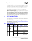
sensors that have been implemented are listed below.
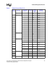
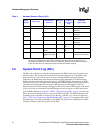
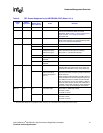
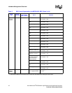
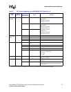
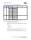
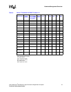
Table 2. Hardware Sensors (Sheet 1 of 3)
Sensor
Number
Sensor Type
Voltage/Signals
Monitored
Monitored
via
Scanning
Enabled
under Power
State
Health LED
(Green to Red)
03h Watchdog Timer IPMC Watchdog
Timer timeout
IPMC Power On/
Off
No change
06h System Firmware
Progress
IPMC Power On No change
07h CPU Critical
Interrupt
PCI SERR IPMC Power On PCI SERR signal
asserted
PCI PERR IPMC Power On PCI PERR signal
asserted
08h Memory Error ECC Multiple Bit
error
IPMC Power On Multiple Bit Error or
Uncorrectable ECC
occurred
ECC Single Bit error IPMC Power On No change
09h Power Unit Payload Power IPMC Power On Soft power control
failure (Offset Bit 05h
asserted