


52 Intel NetStructure
®
MPCBL0001 High Performance Single Board Computer
Technical Product Specification
Hardware Management Overview
3.9.1 Hot-Swap LED (DS10)
The MPCBL0001 SBC supports one blue Hot Swap LED, mounted on the front panel. See
Figure 14, “MPCBL0001NXX SBC Front Panel” on page 71 for its location. This LED indicates
when it is safe to remove the SBC from the chassis. The on-board IPMC drives this LED to
indicate the hot-swap state. Refer to Table 21, “Hot-Swap LED (DS11)” on page 52.
When the lower ejector handle is disengaged from the faceplate, the hot swap switch embedded in
the PCB will assert a "HOT_SWAP_PB#" signal to the IPMC, and the IPMC will move from the
M4 state to the M5 state. At the M5 state, the IPMC will ask the CMM (or Shelf Manager) for
permission to move to the M6 state. The Hot Swap LED will indicate this state by blinking on for
about 100 milliseconds, followed by 900 milliseconds in the off state. This will occur as long as the
SBC remains in the M5 state. Once permission is received from the CMM or higher-level software,
the SBC will move to the M6 state.
The CMM or higher level software can reject the request to move to the M6 state. If this occurs, the
Hot Swap LED returns to a solid off condition, indicating that the SBC has returned to M4 state.
If the SBC reaches the M6 state, either through an extraction request through the lower ejector
handle or a direct command from higher-level software, and an ACPI-enabled OS is loaded on the
SBC, the IPMC communicates to the OS that the module must discontinue operation in preparation
for removal. The Hot Swap LED continues to flash during this preparation time, just like it does at
the M5 state. When main board power is successfully removed from the SBC, the Hot Swap LED
remains lit, indicating it is safe to remove the SBC from the chassis.
Warning: Removing the SBC prematurely can lead to device corruption or failure.
3.9.2 Ejector Mechanism
In addition to captive retaining screws, the MPCBL0001 SBC has two ejector mechanisms to
provide a positive cam action; This ensures the blade is properly seated. The bottom ejector handle
also has a switch that is connected to the IPMC to determine if the board has been properly
inserted.
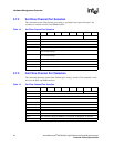
Table 21. Hot-Swap LED (DS11)
LED Status Meaning
Off Normal status
Blinking Blue Preparing for removal/insertion: Long blink indicates activation is in
progress, short blink when deactivation is in progress.
Solid Blue Ready for hot swap