


Intel NetStructure
®
MPCBL0001 High Performance Single Board Computer 67
Technical Product Specification
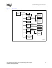
Hardware Management Overview
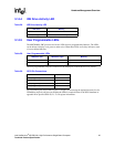
3.14.8 Fibre Channel Port State LEDs
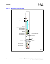
The MPCBL0001 SBC supports two Fibre Channel port state LEDs mounted on the front
faceplate. The LEDs are green and yellow. When this LED is lit, it indicates the port state of each
Fibre Channel port. LED states are shown in the table as follows:
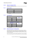
3.15 FRU Payload Control
The MPCBL0001 implements the “FRU Control” command as specified in the PICMG 3.0
Specification. Through this command, the payload can be reset, rebooted, or have its diagnostics
initiated.
The FRU payload can be controlled by a command line via the Intel NetStructure
®
MPCMM0001
Chassis Management Module (CMM). The following CMM commands are supported by the
MPCBL0001.
Note: The user may issue an RMCP command to control the FRU payload as well. Refer to Table 98 on
page 165 for the associated IPMI command information.
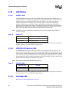
Table 33. Ethernet Controller Port State LED
LED Status (L1 and L5) Meaning
Off No Status
Red/Green/Amber Active status of user-defined function
NOTE: Refer to Figure 14 and Figure 15 for LED (L1 and L5) placement on the
Front Panel.
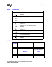
Table 34. Fibre Channel Port State LED (DS2, DS3)
Yellow LED Status (Fibre
Channel 1, left)
Green LED Status (Fibre
Channel 2, right)
Meaning
ON ON Power On
Flashing OFF Loss-of-Sync
ON OFF Signal Acquired
OFF ON On-Line
FLASH FLASH F/W Error
Table 35. CMM Commands for FRU Control Options
FRU Control Options MPCMM0001 equivalent command
Cold Reset cmmset –l bladex –d frucontrol –v 0
Warm Reset cmmset –l bladex –d frucontrol –v 1
Graceful Reboot cmmset –l bladex –d frucontrol –v 2
Diagnostic Interrupt cmmset –l bladex –d frucontrol –v 3